- Details
- Category: Electrical
An intermediate lighting circuit is an extension of a two-way lighting circuit that uses three or more switches to operate a single or multiple light fittings.
In a typical UK home wiring situation, lighting circuits usually incorporate the lighting needs of all of the rooms and areas of a single floor, incorporating one-way, two-way and intermediate switching circuits as required. Generally these circuits are protected by a 6 amp miniature circuit breaker (MCB) and are wired using 1.5mm2 'twin and earth' cable. Previously this might have been a 5 amp MCB or fuse, and 1.0mm2cable. The overriding limitation of the circuit is the maximum wattage that can be supplied. Without taking into account any de-rating factors, the circuit can supply a theoretical maximum of 230 volts x 6 amps = 1380 watts. In general practice, lighting circuit wiring should be planned in such a way as to have a maximum load of 1000 watts. In this way there is a small margin left for third party addition or lamp changes which might affect overall load levels.
The circuit
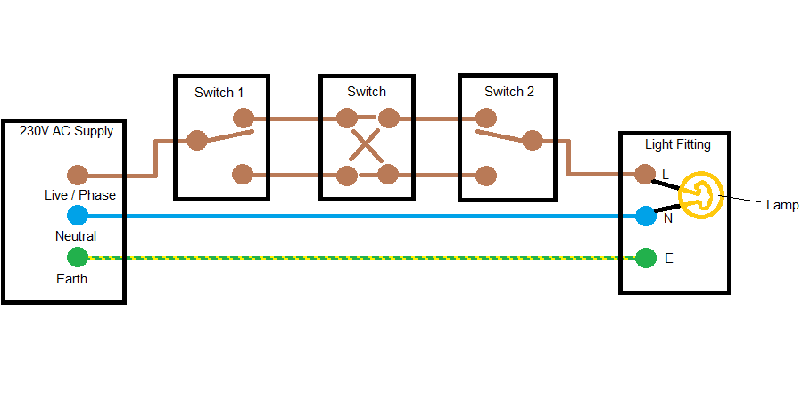
We can see from the picture above that when the switch 1 is switched, electricity can flow from the live supply connection along one of the two 'strapper' wires via the intermediate switch in the middle to switch 2. If switch 2 is also switched to the strapper wire that is currently 'live', electricity can flow to the lamp and pass through the lamp filament to the neutral supply connection, causing the lamp to illuminate. Now when any switch is switched, the switch connects to the other strapper wire and the circuit is broken, causing the lamp to extinguish.
The idea is that any of the switches can cause the lamp to illuminate or extinguish, and this circuit is used in long hallways, stairs, and rooms with more than one entrance/exit. This of course is how the circuit would look if it was done as a bench exercise. Check out our two way lighting circuit article for wiring tips.
NOTE: Always isolate mains power at the consumer unit before starting work.
- Details
- Category: Electrical
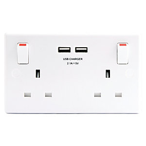 13 amp double socket with USB charger
Here are the major steps to replace an existing 13 amp socket - single or double. Always think safety first.
1. If the socket you are going to replace is undamaged, test the socket with a socket tester, volt stick or mains tester to ensure that power is present.
2. Switch off the power - This is Very Important - Always switch off your power supply at the consumer unit (fuse box) before doing any electrical work. If you have a more modern box fitted with miniature circuit breakers (MCBs), you may be able to identify the correct one and switch it off. If in any doubt, switch off the whole box at the main switch. Ideally you should lock off and flag the MCB or switch to ensure that power is not restored by someone else whilst you are working on the socket. If your box contains fuses rather than MCBs, identify the correct fuse and turn off the main switch. Then remove the circuit fuse and turn on the main switch again to restore power to the rest of the house. If you have any doubts about the actions above please consult a qualified electrician.
3. Use a socket tester, volt stick or mains tester to check that the socket is now unpowered. If you are not sure that you have safely isolated this circuit and that it will remain safely isolated whilst you are working on it, stop work now and contact a qualified electrician.
4. Unscrew the old socket from the wall box. Sockets are normally screwed to the wall boxes with 3.5mm threaded slot head 'socket' screws. You may need to keep the existing screws for use with your new socket (these may be longer than the ones supplied with the new socket), so don't discard these just yet, since at the very least you will be able to measure them so you know what length of screw to get if you need to source replacements.

Double socket rear view. This one has single pole switching (switches Live terminal only) and has USB charging incorporated in the unit
5. On the back of the existing socket you should be able to see the three connections - L (Live) N (Neutral) E (Earth). In the picture above showing the back of a double socket, the Earth connections are marked with the earth symbol inside a circle, rather than E. This is common and depends on the manufacturer's preference. Each connection should already have at least one wire connected to it. Make a note of the existing wire positions, colours and connection markings. Label each wire clearly with the terminal it is connected to. Wiring colours in the UK were changed in April 2006.
The table below shows the wiring colours for older installations (pre-April 2006) and all new wiring, and the correct terminals to connect each wire into:
| Older Wiring (pre 2006) | New Wiring (post 2006) | Connects to: |
| Red | Brown | L or Live |
| Black | Blue | N or Neutral |
| Green or Yellow/Green | Yellow/Green | E or Earth |
The green/yellow earth wire connects both to Earth on the socket and to the earth terminal of the mounting box (where provided).
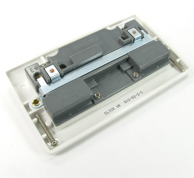
Double socket rear view. This one has double pole switching (switching on Live and Neutral terminals). Note new screws supplied with socket.
6. Visually match the connections on the back of the new socket with those on the old socket. Check that wires will be able to reach if the layout is slightly different.
7. Disconnect the old socket and set it aside.
8. Connect the new socket, being very careful of connection placement. Tighten terminal screws securely and give wires a good tug to check they're firmly fastened within the wire terminals. Make sure that the wire's insulation is not trapped under the terminal screws. Make sure that bare wire is inside the terminal connections only, no bare wires should be seen outside of the terminals. Make sure any Earth wires are correctly sleeved.

Correctly connected socket. Wires are to be kept away from possible pinch or damage points, the above would need a little adjusting of live and earth wires.
9. Check again connections are correct and secure. Incorrect or loose connections can cause electrical faults which can lead to fires or electrocution.
10. Screw the socket to the wall box (using the new supplied socket screws, or re-using the existing ones) and level off.
11. Switch on the mains power to the circuit. If refitting a fuse, switch off the mains switch before doing so, then switch on.
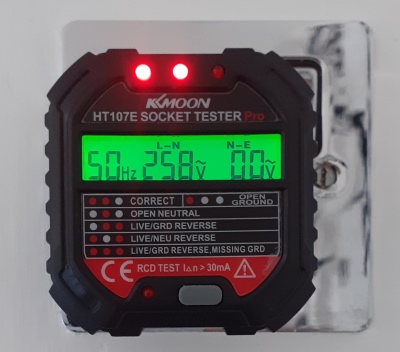
Socket tester in use. Both sockets on a double should be tested.
12. Test the socket using a socket tester, volt stick or mains tester. Socket testers are the safest items to use. These units are quite inexpensive and can give an indication of correct polarity and earthing in addition to merely indicating the presence of electricity. A sound investment if you plan to change more than one socket in your lifetime, and gives some peace of mind.
Tools required
Ideally the tools you will need are as follows:
- Side cutters or wire stripper
- Socket tester
- Volt stick or mains tester
- 5.5mm Flat blade screwdriver
- Earth sleeving
- socket screws - 3.5mm x 25mm or 3.5mm x 50mm
- Details
- Category: Electrical
A two-way lighting circuit is a circuit that uses two switches to operate a single or multiple light fittings.
In a typical UK home wiring situation, lighting circuits usually incorporate the lighting needs of all of the rooms and areas of a single floor, incorporating one-way, two-way and intermediate switching circuits as required. Generally these circuits are protected by a 6 amp miniature circuit breaker (MCB) and are wired using 1.5mm2 'twin and earth' cable. Previously this might have been a 5 amp MCB or fuse, and 1.0mm2cable. The overriding limitation of the circuit is the maximum wattage that can be supplied. Without taking into account any de-rating factors, the circuit can supply a theoretical maximum of 230 volts x 6 amps = 1380 watts. In general practice, lighting circuit wiring should be planned in such a way as to have a maximum load of 1000 watts. In this way there is a small margin left for third party addition or lamp changes which might affect overall load levels.
The circuit
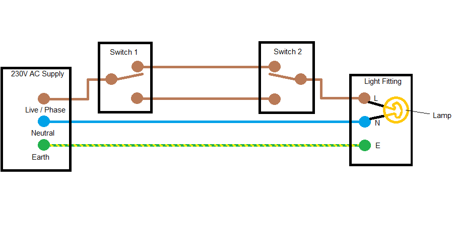
We can see from the picture above that when the switch 1 is switched, electricity can flow from the live supply connection along one of the two 'strapper' wires to switch 2. If switch 2 is also switched to the strapper wire that is currently 'live', electricity can flow to the lamp and pass through the lamp filament to the neutral supply connection, causing the lamp to illuminate. Now when either switch is switched, the switch connects to the other strapper wire and the circuit is broken, causing the lamp to extinguish.
The idea is that either switch can cause the lamp to illuminate or extinguish, and this circuit is used in long hallways, stairs, and rooms with more than one entrance/exit. This of course is how the circuit would look if it was done as a bench exercise.
Wiring circuits
In practice, a lighting circuit would supply more than just two switches and one light fitting. We are merely looking at a single segment of a typical circuit. To achieve the same desired effect as the circuit drawing above, there are three basic ways in which a domestic lighting circuit could be wired using UK 'twin and earth' and 'three-core and earth' cable.
1. Loop-in at the light.
This is the most favoured method, as it keeps most of the permanently live 'mains feed' cabling in the ceiling void or loft space out of harm's way. A twin and earth cable is run from the consumer unit to the first light fitting. Another is run from the light fitting to the first switch. Another from the light fitting to the next light fitting, or light / switch combo. Finally, a three-core and earth cable is run from the first switch to the second switch. There are at least two variations of connecting up the first switch, which are shown below.
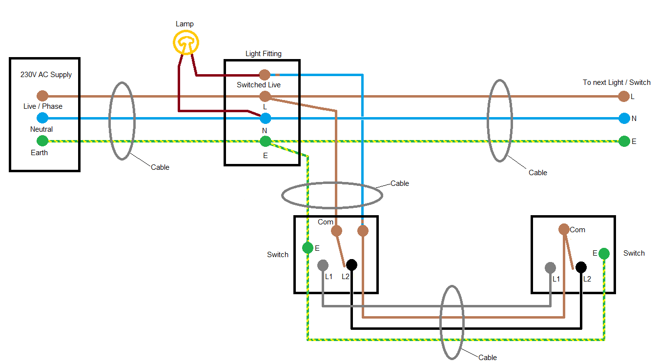
The method above employs a piece of 'choc block' or 'connector strip' at the first switch to join the wire connected to 'com' on the second switch to the switched live connection from the light fitting. The method below does away with the need for a piece of 'choc block' to join wires in the first switch, arguably at the cost of circuit clarity to the DIY enthusiast.
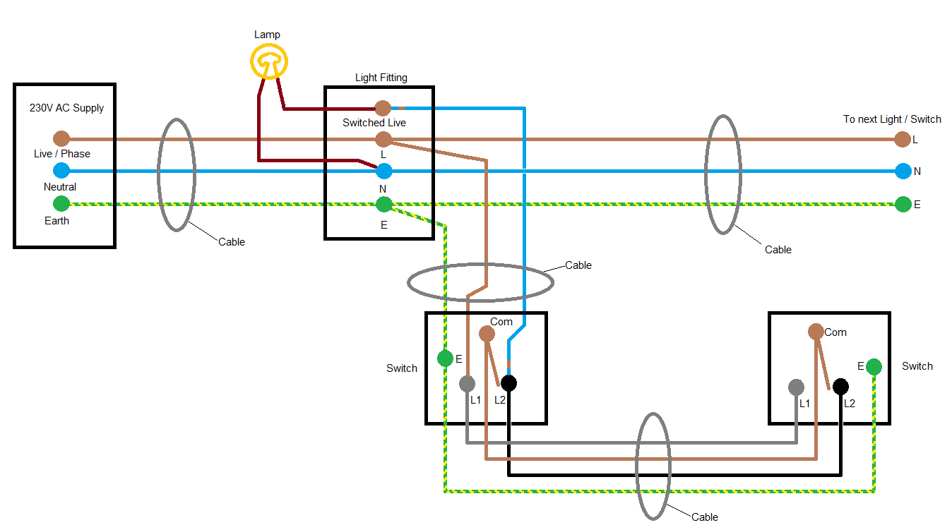
NOTE: Switching off the light at the switch DOES NOT isolate mains electricity from the light fitting or switches - always isolate mains power at the consumer unit before starting work.
2. Junction Box.
This method of wiring lighting circuits is often used where open loft spaces allow easy access to the junction box. A 'mains feed' cable is run from the consumer unit to the junction box, which is usually placed centrally within the loft or floor area. A cable of the correct type is then run from each light fitting and from each switch back to the junction box. Alternatively, the switches of a two-way system can be wired using a twin and earth cable from the junction box to the first switch, then a three-core and earth from the first switch to the second switch. The junction box method uses more cable than the previous method, but allows for easy addition of further lights or switches. There are at least three variations of wiring or connecting up the circuit, which I show below.
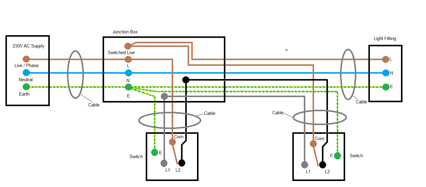
Using the wiring method above, each switch cable is wired back to the junction box, and the strapper wires are joined in their own connectors.
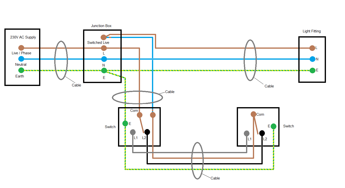
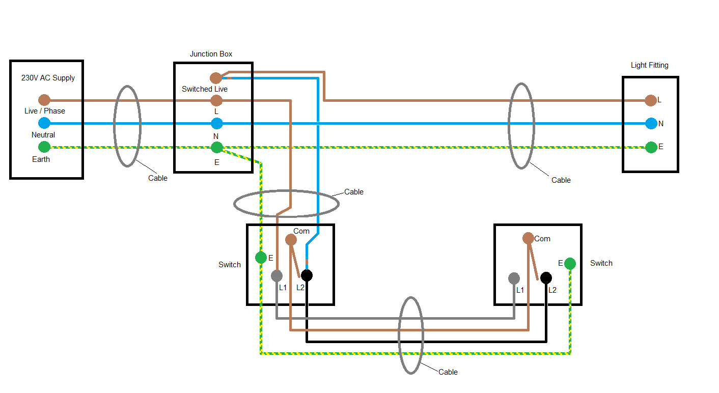
Using the two wiring methods above, only the first switch is wired back to the junction box, using twin and earth cable. The second switch is wired to the first using three core and earth. Two methods of connecting the first switch are shown. Cable identification - especially at the junction box, is paramount using this method, as switches and light fittings could be easily confused or jumbled, causing unwanted faults or mis-operation.
NOTE: Always isolate mains power at the consumer unit before starting work.
3. Loop-in at the switch.
This is the least favoured method of wiring a lighting circuit, since it means there are permanently live 'mains feed' cabling runs within walls to almost every switch. Also, switched live, neutral and earth connections may become squashed inside the switch accessory box (especially the shallow ones), causing circuit faults.
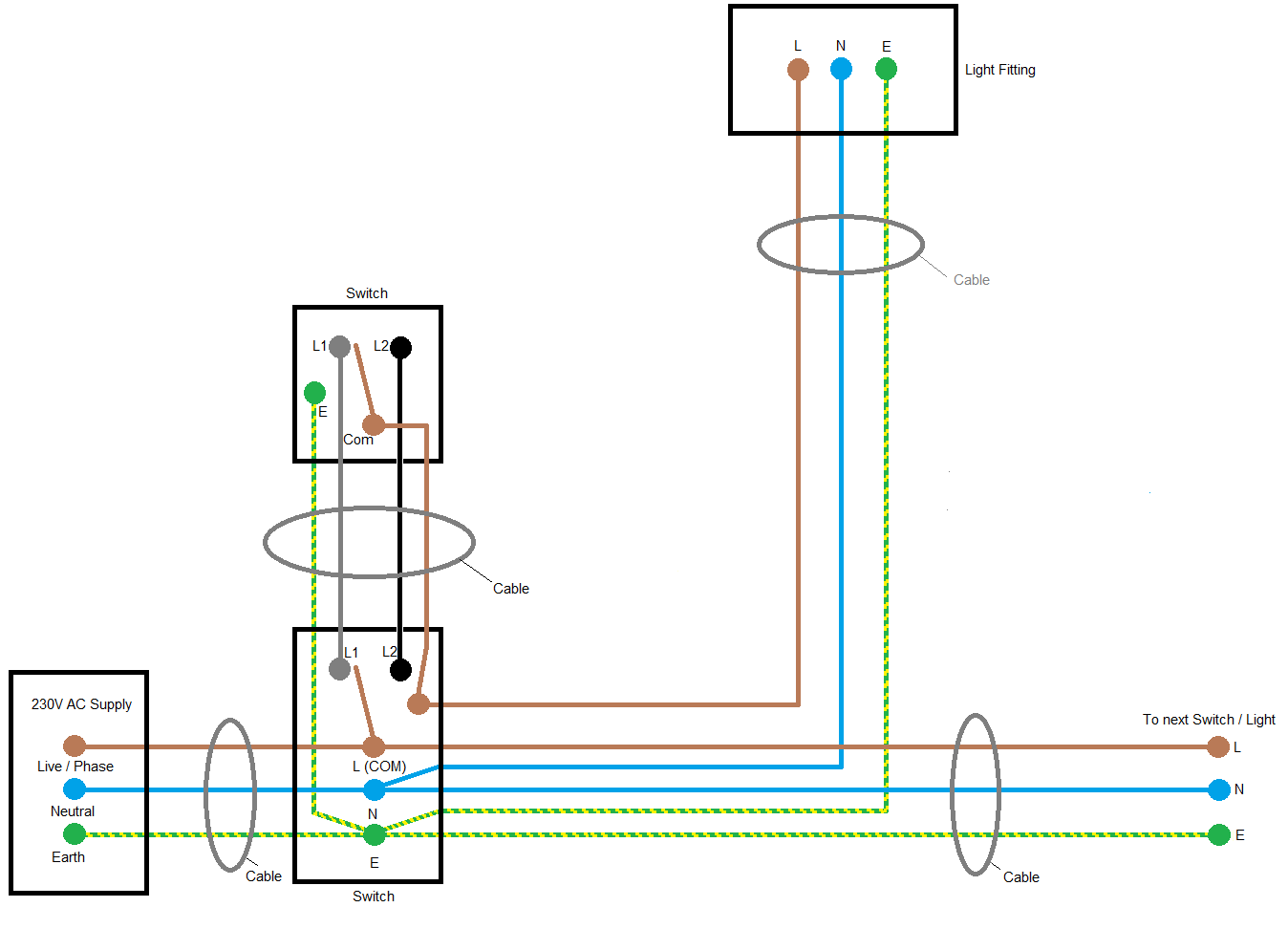
With this method a twin and earth cable is run from the consumer unit to the first switch. Another is run from the first switch to the light fitting(s). Another to the next switch / light combo, and finally, a three-core and earth cable is run from the first switch to the second switch. The connections at the first switch can of course be re-configured to remove the 'choc block' on the switched live. However this requires three 1.5mm2 wires try to share a connection on the switch which might not be large enough. The first switch becomes quite busy with wires and this only gets worse if more switches are required on the same switch plate.
NOTE: Always isolate mains power at the consumer unit before starting work.
- Details
- Category: Electrical
A one-way lighting circuit is a circuit that uses a single switch to operate a single or multiple light fittings.
In a typical UK home wiring situation, lighting circuits usually incorporate the lighting needs of all of the rooms and areas of a single floor, incorporating one-way, two-way and intermediate switching circuits as required. Generally these circuits are protected by a 6 amp miniature circuit breaker (MCB) and are wired using 1.5mm2 'twin and earth' cable. Previously this might have been a 5 amp MCB or fuse, and 1.0mm2cable.
The overriding limitation of the circuit is the maximum wattage that can be supplied. Without taking into account any de-rating factors, the circuit can supply a theoretical maximum of 230 volts x 6 amps = 1380 watts. In general practice, lighting circuit wiring should be planned in such a way as to have a load of 1000 watts or less. In this way there is a small margin left for third party addition or lamp changes which might affect overall load levels.
The circuit
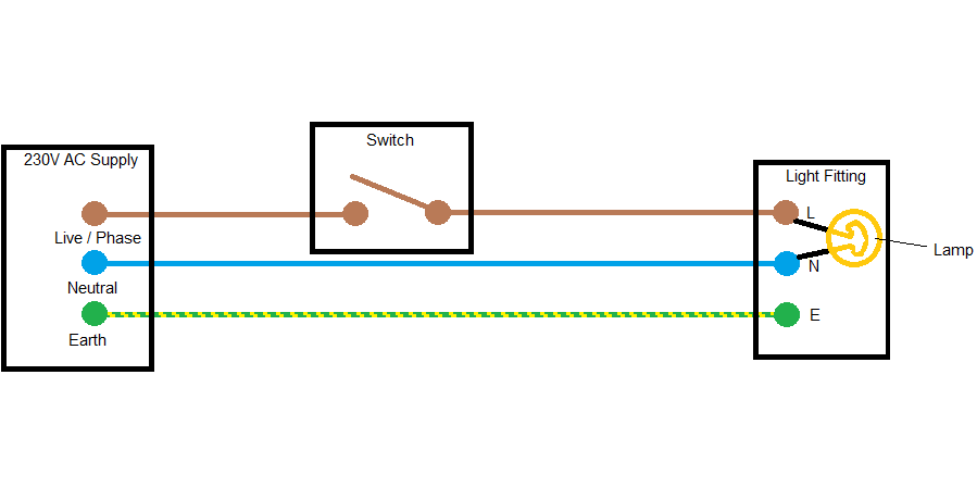
We can see from the picture above that when the switch is closed, electricity can flow from the live supply connection to the lamp and pass through the lamp filament to the neutral supply connection, causing the lamp to illuminate. When the switch is opened, the circuit is broken, causing the lamp to extinguish. This of course is how the circuit would look if it was done as a bench exercise.
Wiring circuits
In practice, a lighting circuit would supply more than one switch and one light fitting. We are merely looking at a single segment of a typical circuit. To achieve the same desired effect as the circuit drawing above, there are three ways in which a domestic lighting circuit could be wired using UK 'twin and earth' cable.
1. Loop-in at the light.
This is the most favoured method, as it keeps most of the permanently live 'mains feed' cabling in the ceiling void or loft space out of harm's way. A cable is run from the consumer unit to the first light fitting. Another is run from the light fitting to the switch. Another from the light fitting to the next light fitting, or light / switch combo, until the circuit is complete. This wiring method is easy to identify due to the number of cables at the light fitting.
It can be confusing to the DIY enthusiast, especially if they have disconnected the light without marking up the connections beforehand, since there could be as many as four twin and earth cables at the first fitting in a room. In this instance, colour-to-colour wire replacement at the light means that the light illuminates immediately when the mcb is reset, then when the switch is closed (to try to switch off the light), the resulting short-circuit welds the switch closed permanently and trips the MCB. Best practice is to identify the switched live wire clearly at the switch and at the light fitting before taking the old fitting down. These circuits have often led to call outs for electricians when DIY efforts have gone wrong.
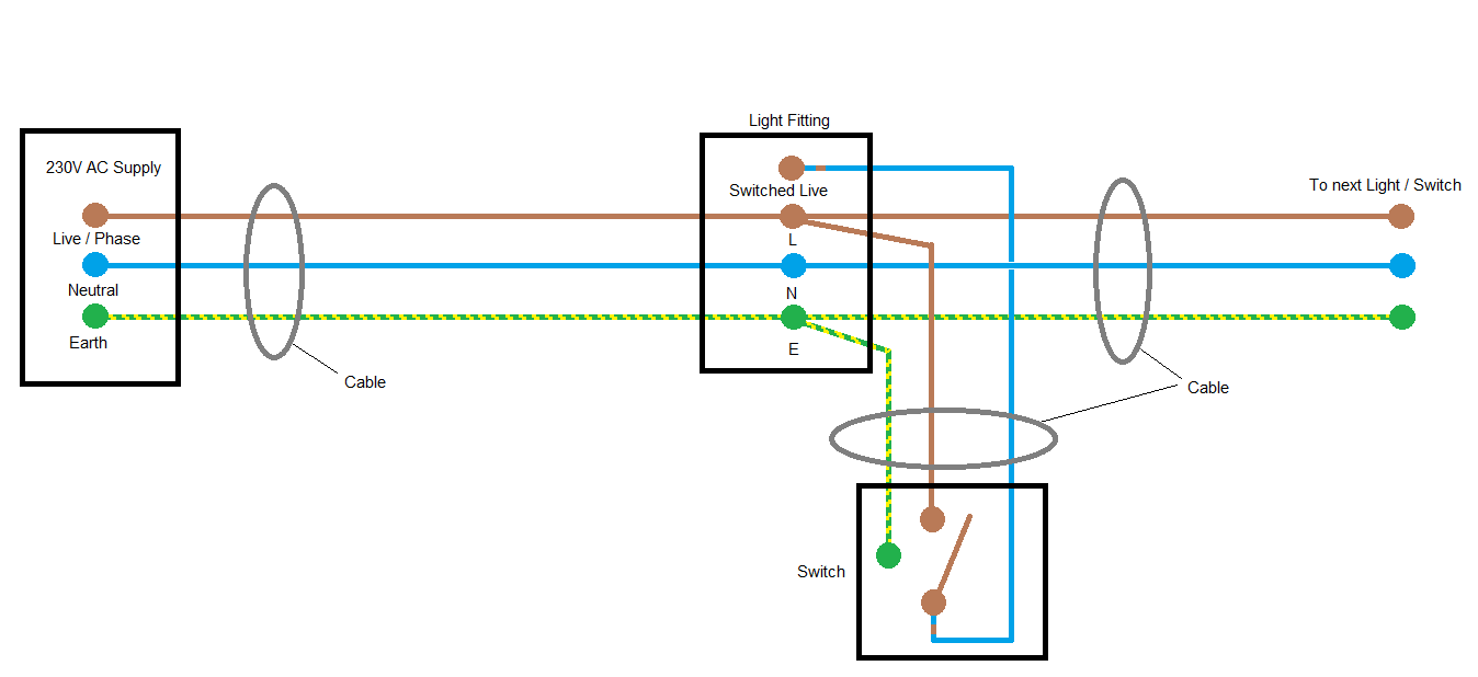
NOTE: Switching off the light at the switch DOES NOT isolate mains electricity from the light fitting or switch - always isolate mains power at the consumer unit before starting work.
2. Junction Box.
This method of wiring lighting circuits is often used where open loft spaces allow easy access to the junction box, or containment conduits have been installed prior to cabling. A 'mains feed' cable is run from the consumer unit to the junction box, which is usually placed centrally within the loft or floor area. A cable is then run from each light fitting and from each switch back to the junction box.
This method uses a little more cable than the previous method, but allows for easy addition of further lights or switches. This wiring method is slightly harder to identify than the one above, however it becomes apparent if both light fitting and switch are inspected, as only the minimum required cables will be present at these locations. Cable identification at the junction box is paramount using this method, as switches and light fittings could be easily confused or jumbled, causing unwanted faults or mis-operation.
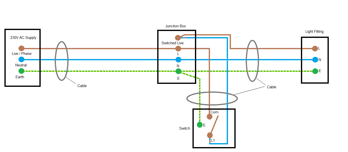
NOTE: Always isolate mains power at the consumer unit before starting work.
3. Loop-in at the switch
This is the least favoured method of wiring a lighting circuit, since it means there are permanently live 'mains feed' cabling runs within walls to each switch. Also, neutral and earth connections may become squashed inside the switch accessory box (especially the shallow ones), causing circuit faults.
With this method a cable is run from the consumer unit to the first switch. Another is run from the switch to the light fitting(s). Another to the next switch / light combo, until the circuit is complete. This wiring method is easy to identify due to the number of cables at the switch. It requires only that the live and switched live are identified at the switch.
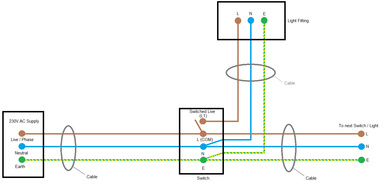
NOTE: Always isolate mains power at the consumer unit before starting work.
- Details
- Category: Electrical
Voltage - also known as a potential difference, is needed across an electrical component is needed to make a current flow through the component.
In small circuits, cells or batteries often provide the voltage needed for the circuit to work. Each circuit has it's own voltage and current requirements, and this is governed by the components you wish to add to the circuit.
For instance if you connect a 3 volt rated filament bulb to a battery giving 1.5 volts, it would not work as intended (it would glow dimly).
Conversely if you connect a 3 volt rated filament bulb to a battery giving 4.5 volts, it would also not work as intended (it may also be damaged).
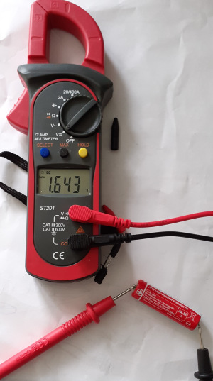
Measuring DC voltage
Voltage is measured in volts, (V).
The voltage across a component in a circuit can be measured using a voltmeter. This must be connected in parallel with the component in a circuit.
Below is an image taking a voltage reading from a new battery - the multimeter is set to measure DC (Direct Current) Voltage, which is the kind you get from a battery.
If you add a simple circuit to the battery and measure the voltage across each of the components, the voltages measured should add up to the total voltage supplied by the battery.
