Network Cabling
Network cabling (a.k.a. structured cabling) nowadays is generally wired using Category 5e (low speed), Category 6, Category 6A, Category 7 or maybe even Category 8 (high speed) cables, depending on the required design and expected traffic. These cables usually flow through the building on supported containment like cable basket or cable tray from the comms cabinet out to the network sockets, one cable for each socket port required. Usually extra sockets over and above the bare minimum required are fitted, (known as flood wiring) since it is more cost effective to install more than you really need at the outset than come back to install more later.
So what is a Category whatever cable?
Anyone who has plugged their computer into a network or broadband Internet connection such as cable or ADSL, has used an Ethernet cable for this. Ethernet cables are the standard cables commonly used to connect a modem to a router or network, and likewise, to connect a network switch or hub to a computer's network interface card (NIC).
Not all Ethernet cables are created equal. Ethernet cable technology has been evolving since the beginning of the Ethernet standard back in 1985. Many different categories of Ethernet cable have been developed, and each category has different specifications as far as shielding from electromagnetic interference, data transmission speed, and the possible bandwidth frequency range required to achieve that speed. Some confusion can arise when looking at all of the available options for Ethernet cabling. The standard gauge sizes (AWG) are also different in the different categories of cable, and this can influence the end results for both quality and speed. Luckily, the category of cable is usually clearly printed on the cable's sheath, so there can be no doubt as to the type of cable being used for existing networks if you are adding to it. There are also certain types of cables recognized as common industry standards. Described below are a few of the most common categories of Ethernet cable that are used in networks today. We are not going to look at the obsolete types, so for this reason we will jump straight to Category 5e Cable.
The major categories of Ethernet cables
Category 5e
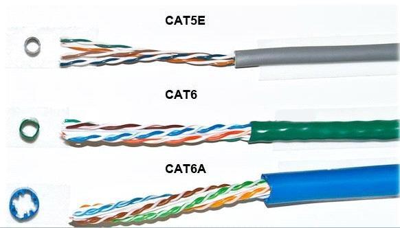
The Category 5 enhanced (Cat 5e) is typically installed as an Unshielded Twisted Pair (UTP) cable and is an improved version of Cat 5 cable, which is optimised to reduce crosstalk, or the unwanted transmission of signals between data channels. This category works for 10/100 Mbps and to a lesser degree, 1,000 Mbps (Gigabit) Ethernet. Bandwidth is also increased with Cat 5e cables, which can support a maximum bandwidth of 100 MHz. Cat 5e cables are backward-compatible with Cat 5 cables. Small Category 5e networks are still being installed today, however many customers have moved up to Cat 6 or Cat 6A cabling.
Category 6
One of the major differences between Category 5e and the newer Category 6 (Cat 6) is in transmission performance. While Cat 5e cables can handle Gigabit Ethernet speeds, Cat 6 cables are certified to handle Gigabit Ethernet with a bandwidth of up to 250 MHz. Cat 6 cables have several improvements, including better insulation. These improvements provide a higher signal-to-noise ratio, and are better suited for environments in which there may be higher electromagnetic interference. Some Cat 6 cables are available in duct grade (ruggedised) sheath, shielded twisted pair (STP) forms or unshielded twisted pair (UTP) forms. Cat 6 cable is also backward-compatible with Cat 5 and cat 5e cables. Cat 6 cables are slightly more complex to terminate, due the central core of insulation around which the wire pairs are wound.
Category 6A
Category 6A cable, or Augmented Category 6 cable, improves upon the basic Cat 6 cable by allowing 10,000 Mbps data transmission rates and effectively doubling the maximum bandwidth to 500 MHz. Category 6a cables are available in UTP or STP form and require specific Cat 6A Plugs for termination, STP versions must have specialised connectors that ground the screen/ drain to a metal shield. With each successive category, there has been an increase in data transmission speed and bandwidth. This cable is best installed using patch panels, data network sockets and patch leads rather than crimping plugs on each end.
Category 7
Category 7 cable is a stiffer cable which is slightly more difficult to install than Cat 6A. It is slowly being added to the specs for higher traffic networks and new installs, which will in turn bring prices down and allow wider adoption.
Category 8
Category 8 cable is the current high budget solution for maximum bandwidth. For this reason and others the cable has not yet seen high levels of adoption.
When installing a new network cabling installation, the highest cable categories are recommended, but only if all of the other equipment on the network is capable of similar speeds. Otherwise, expensive cables are only as fast as the slowest piece of hardware on the network.
Other qualities of Ethernet cables to consider
There are a few important considerations that apply to all Ethernet cables. Data transmission rate and bandwidth both decrease as the cable length increases, so the shorter the cable length, the better. For 10/100/1000BASE-T networks, or those that have maximum speeds of 10, 100, or 1000 Mbps, including all the aforementioned cable types, 100 meters is the maximum allowable cable length before the signal degrades unacceptably. Usually this is stated as 90 metres, to allow up to 10 metres for patch leads. For category 6A cables running at 10 Gbps speeds, 55 meters is the maximum allowable length, and even this length is only available in low interference environments.
Ethernet cable connectors
The ends of Ethernet cables that connect into a computer Network Interface Card (NIC), router, or other network device are known by several names. Jack, modular connector or plug are the most commonly used terms. Ethernet cables can be purchased in many lengths, up to 500 metres. Short lengths of Ethernet cable are usually sold with the connectors already installed (known as patch leads), but for custom installations requiring non-standard lengths, cable is often sold in bulk quantities, and connectors must be installed on the ends.
The most common type of connector for Ethernet installations is referred to as an "RJ-45" connector. It is officially known as an ‘8P8C’ connector, but this term is rarely used in the field, and the term "RJ-45," which was the telephone industry's term for this connector's wiring pattern, has become the customary colloquial name for the connector itself. Categories 3 to 6 all use similar versions of the RJ-45 connector, but Cat 6A and Cat 7 use different versions of the connector.
RJ-45 pin assignment
There are two industry standard pin assignment configurations for RJ-45 connectors: T568A and T568B.
The T568B standard is the most used standard, but T568A type connections are by no means obsolete.
In every case, the specifications of the cable, such as its category, whether or not it is shielded, and whether or not it needs to be grounded, must match the specifications of the connector.
Of course patch leads are widely manufactured, and leads of several lengths and colours are available quite cheaply. Even for a single lead, buying a pre-made one is likely to be the most cost-effective route. But what if you need to make your own lead?
Here's what you'll need to source:
A length of cable
If you are using cable measured and cut from a reel (rather than having a whole box or reel to hand), always allow yourself some extra cable to cover for any initial termination mistakes you might make. For longer lead lengths that may be linking rooms or levels in a building, keep the cable away from mains wiring, pipes or vents, and sharp edges.
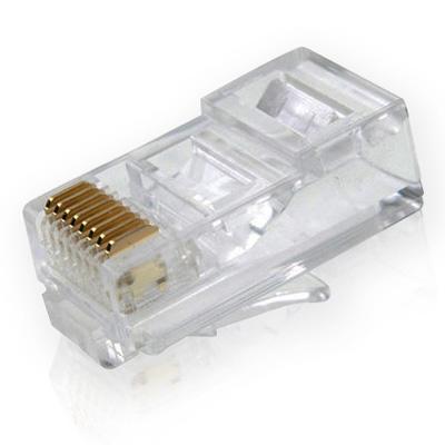
RJ-45 plugs
These are readily available from blister packs of 10 up to boxes of 500. You will need two for each patch lead, but spares are always handy. Make sure you buy the correct version of the plug to match the cable you have.
RJ-45 crimp tool
These are used to cut and strip the cable, as well as 'crimp' (squash) the brass plug terminations and strain relief clamp of the plug onto the cable.
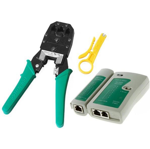
Crimp tool, Cable stripper and lead tester
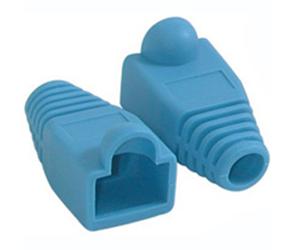
RJ-45 plug boots
An optional item that you might consider, especially if you plan to plug/unplug the patch lead often, as the plug boot helps to take some of the flexing strain from the cable as it enters the plug.
Cat 5 cable stripper
A handy tool though only really necessary if you plan to make lots of leads, the stripper tool cuts into the cable jacket to the correct depth, leaving the wires underneath undamaged.
Wire cutters and craft knife
Wire cutters are handy for cutting the cable and wires to the correct depth. You can (if you are very careful) use a craft knife to remove the cable jacket.
Lead tester tool
A useful device which helps to prove your patch leads are correctly terminated.
Making your own patch leads
For Cat 5e cables, find the end of the cable and push on a RJ-45 boot, circular end first (if you are using them) then strip between 25 - 50mm of outer cable jacket from the cable. To do this, either ring around the jacket (being careful not to damage the inner conducting wires), gently with a craft knife and pull off, or use a UTP cable stripping tool. Once you have done this, you will have exposed the cable wire pairs, like this:
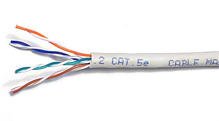
Separate the four twisted wire pairs from each other, and then unwind each pair, so that you end up with 8 individual wires. Straighten and flatten the wires out as much as possible, since they'll need to be very straight for proper insertion into the RJ-45 connector.
I find that if I have stripped off a slightly longer length of the outer cable jacket than is strictly necessary, that unwinding the pairs and straightening them out is less fiddly. You can always cut the excess wire off.
Once you have done this, hold the cable with the wire ends facing away from you. From left to right, arrange the wires in a flat, side-by-side ribbon formation, placing them in the following order: white/orange, solid orange, white/green, solid blue, white/blue, solid green, white/brown, solid brown. (see picture below)
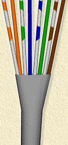
Hold an RJ-45 plug beside the cable. The end of the cable jacket should line up with the step, which is about a third of the way along the plug, and the wires must be long enough to reach to the far end of the plug. If the wires are too long, trim them back, making sure that you cut the wires square across the 'ribbon' you have made out of the individual wires.
Holding the RJ-45 connector so that its brass coloured pins are on top of the plug at the far end, and the plug-clip side is facing down, carefully insert the flattened, arranged wires into the connector, pushing until all of the wire ends stop in the far end of the plug. Note that this will not happen if you have not previously cut the wires 'square', or if you have cut them too short. For strength of connection, also make sure that the cable jacket fits as far as possible into the connector. The cable/plug assembly should now look like this:
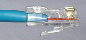
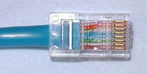
Check to make sure that the wire ends are touching the end of the plug, and that the wires have aligned into the plug in the correct order. If they are not, remove the cable from the plug, re-arrange the wires into the proper order, and re-insert. Remember that once the RJ-45 plug is crimped onto the cable, it's permanent. If you realise that a mistake has been made in the wire order, or that one of the wires is too short after you have crimped the plug, you'll have to cut the plug off and start over - now with a slightly shorter bit of cable.
Okay. So having double checked the wires are in the correct order etc, and the cable jacket is fully inserted, fit the prepared plug/cable assembly into the RJ-45 slot in your crimping tool. Firmly squeeze the crimper's handles together until you can't go any further. Release the handles and repeat this step to ensure a proper crimp.
Now push up the cable boot (if you fitted one) to cover the back end of the plug, measure off the cable you need for your lead, and cut to length.
Repeat the cable termination process with the other end of the cable. Once you have done this, you are free to test your new patch lead with a test unit. All being well with this, you can then plug-in and use the lead.
Remember to label the cable ends with a meaningful ID so you know what it is for.
The Colour Standards
TIA/EIA-568 is a set of telecommunications standards from the Telecommunications Industry Association (TIA), an offshoot of the Electronic Industries Alliance (EIA). The standards address commercial building cabling for telecommunications products and services, e.g computer networks. Perhaps the best known features of TIA/EIA-568 are the pin/pair assignments for eight-conductor 100-ohm balanced twisted pair cabling, known as Ethernet. These assignments are named T568A and T568B. You can use either version of the colour standards without detriment, as long as you stay to the same standard throughout your install. Below is a picture of how the colour standards differ inside a RJ-45 plug.
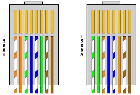
You'll notice from the drawing above that we previously described the making of a lead to the T568B standard, with both ends having this colour layout. However occasionally a 'crossover lead' is required (this is getting rarer).
If you need to make a crossover patch lead, simply make one end of the lead to T568A standard, and one end of the lead to T568B standard.
Do’s and Don’t’s of installing network cabling
Here are some common issues that can drastically affect network performance.
Do Keep the cable well away from mains wiring, hot pipes or heat vents, and sharp edges.
Don’t Kink, fold or twist the cable during install. This squashes the wires inside the cable and can upset the twist ratio and displace the wire insulation inside the cable, which can cause short circuits. The twist ratio is important for maintaining network speeds. Damaged cables immediately provide poorer performance or failure.
Do Use velcro straps to secure Cat 6/6a/7 cables on tray or basket runs, as cable ties can squash the cable including the central air gap, which badly degrades network performance. Cable ties where absolutely necessary should be kept to a minimum and be as loose as can be tolerated for a quality install.
Don’t Bend the cables sharply around corners. This is why most dado or compartment trunking systems have sweeping bends. This applies as much to mains cables as it does to networks. Network cables should not be jammed together into the smallest mini-trunking possible and subjected to sharp right angle bends. If this is your only option, it will definitely provide slower network speeds.
Do keep your cable runs as short as possible whilst still providing a neat finish. Cable runs should ideally be less than 90 metres, and on no account be more than 100 metres in total, including patch leads.
Don’t strip and untwist any more of a cable than is absolutely necessary to terminate it correctly. This again affects the twist ratio on the cable which will adversely affect network speed.
Do Terminate cables using the correct IDC punch down tools or crimpers. Don't be tempted to use other tools for this, you might get it to work, but at the cost of network speed.
Don’t install cables in a spider web configuration, always try to keep network cables to contained routes and ensure they are neatly installed and secure. Cables should be neatly loomed into comms cabinets or hub points where provided.
