- Details
- Category: IP Networks
How to change your laptop or PC IP address
You may wish to communicate with a new device you have added to your Local Area Network in order to change it's IP address or change some other configuration features. Sometimes you need to change your PC / laptop's IP address to match the range being used by the new device temporarily. To do this via windows 10, search for Control Panel, then chose Network and Internet, click on Network and Sharing Centre, then choose 'change adapter settings' from the left hand menu.
Choose the Local Area Connection and double click on it to open your Local Area Connection to view it's properties.
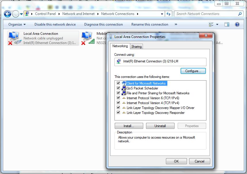
Click on Internet Protocol version 4 (TCP/IPv4) to view the IPv4 properties.
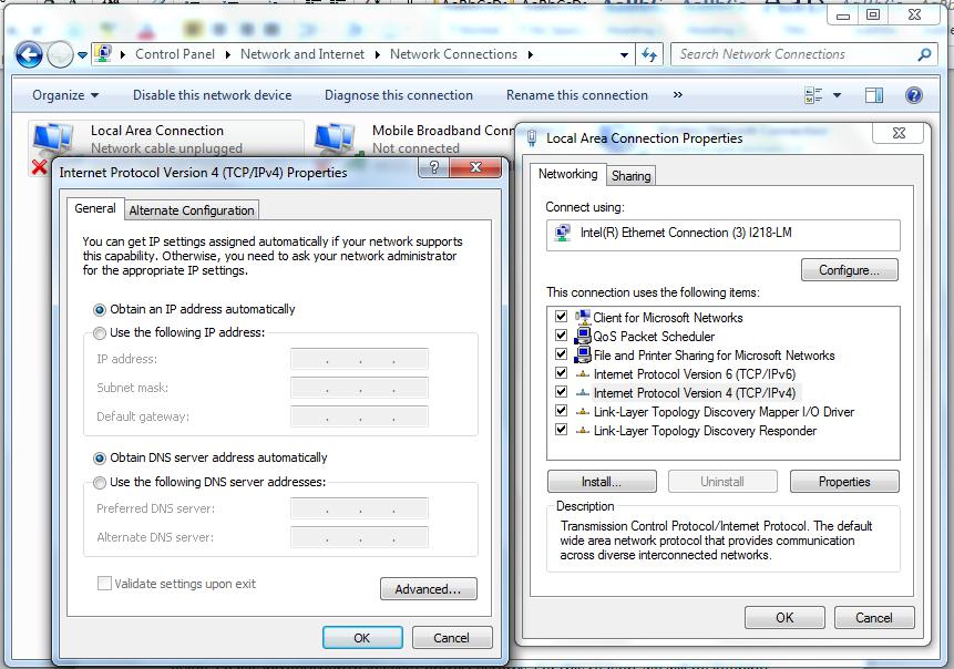
From the picture above, we can see that our network connection is configured to accept an IP address from the DHCP server (set to obtain an IP address automatically).
To change to a static IP address, click the ‘Use the following IP address:’ radio button and input a valid, unused IP address within your new device's IP range.
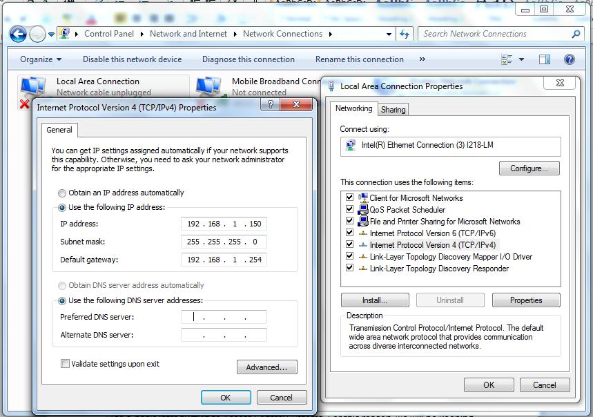
Our new device was supplied with a default IP address of 192.168.100. I have chosen 192.168.1.150 to be within the same network range (192.168.1) as the new device, but with a different node address (150 rather than 100) to the device. The subnet mask applied is what decides which numbers are part of the network range and which are for devices. The subnet mask shown above is the standard one for class C networks using this network address. On this occasion I have entered a default gateway IP address. This address is not always required, especially on closed networks, where it may be left blank.
Click OK to complete the change and test your link to the new device.
- Details
- Category: IP Networks
Why Bother with IPv6?
IPv6 (IP version 6) was designed to replace the ageing IPv4 addressing system, which was conceived prior to the widespread use of the internet. As a result of the internet’s booming popularity, public IPv4 address space has almost run out, and more and more businesses and institutions have migrated to IPv6 - you may not have noticed that this has happened.
If you checked out our article on IPv4 IP addressing, you already know that an IPv4 IP address is 32 bits long. An IPv6 IP address is 128 bits long, which means that, in theory, there are 340,282,366,920,938,463,463,374,607,431,768,211,456,2128 (340 billion billion billion billion) addresses available, which is a great deal more than the 4.3 billion addresses available with the 32 bit IPv4 system.
Since this technology will take over from IPv4 in future, many IP devices are now able to be addressed using IPv4 or IPv6 schemes. Some devices use both simultaneously. One current snag of swapping over to IPv6 is that any network switches and routers need to be checked for IPv6 compatibility, and may need to be configured to handle IPv6 data if they are in fact compatible. This will soon filter out as IPv6 sees wider use.
So IPv6 is already with us, if not noticeably ubiquitous yet, but will eventually become the main standard for IP networks, so it’s worthwhile to get a handle on it now.
So what does IPv6 look like?
IPv6 is similar in many ways to IPv4 addressing. Basically every device has to have a unique IP address, there is name resolution of IPv6 addresses to host names, dynamic addressing, static addressing, routing, etc. as with IPv4.
However when drawing up the specification for IPv6, rather than doing things exactly like IPv4, IPv6 improved upon a handful of things to simplify addressing, routing, improve security, and improve performance and efficiency of IPv6 communications compared to IPv4. So as much as IPv6 addresses themselves are really long and cumbersome, what was done with the IPv6 system actually makes it more efficient.
So the following is some terminology in IPv4 terms and how these concepts are addressed in IPv6:
IP Address: Each device will have an IP address still, but instead of an IPv4 address, it’ll have an IPv6 address. Other than the length and slightly different look, this concept is identical.
Subnet Mask: We used to do subnet masks in IPv4 with notation like 255.255.255.0, or CIDR notation, e.g. /24.
IPv6 uses it's own version of subnet masking which is similar to CIDR notation. We now indicate subnets using a slash and a number that denotes the masking. So for a local area network that would look like:
xxxx:xxxx:xxxx:xxxx:xxxx:xxxx:xxxx:xxxx /48 (an IP range with subnets) or
xxxx:xxxx:xxxx:xxxx:xxxx:xxxx:xxxx:xxxx /64 (an IP range without subnets).
But when you actually key in the IPv6 address on a system, that /48 or /64 will refer to the use (or not) of a hexadecimal number that’ll be in the middle (the fourth “number” from the left) of the IPv6 Address.
So when you see an IPv6 address, while it is really long, it actually includes the Network Address : Subnet : Device IP Address Information in that long address string. We will look at this in more detail later.
Default Gateway Address: The concept of the network gateway in IPv6 is the same as in IPv4, a default gateway address will be designated, which decides where traffic can be routed out of the current subnet (technically the IPv6 Default Gateway address is not a formal standard in IPv6, however Microsoft has included a Gateway setting in their Windows IP Configuration properties page)
What is the equivalent of private network addressing in IPv6?
So how about Private (internal) network addresses, do they exist in IPv6? The answer of course is yes. So if you are just fiddling around with IPv6 on your own private network, or you want to use the equivalent of network address translation (NAT) where you have private addresses for your internal servers and systems, then you can use IPv6 private addressing, using the Unique Local Address (ULA) range, or the Link-Local address range. In the IPv4 world, private addresses include the ranges 10.0.0.0 to 10.255.255.255, 172.16.0.0 to 172.31.255.255, and 192.168.0.0 to 192.168.255.255. In the IPv6 world, the ULA space is fc00 and the link-local space is fe80, So
fc00:xxxx:xxxx:xxxx:xxxx:xxxx:xxxx:xxxx
Indicates a ULA address. <
fe80:xxxx:xxxx:xxxx:xxxx:xxxx:xxxx:xxxx
Indicates a link-local address.
Do note though, that if you use Unique Local Addressing or link-local addressing in IPv6, these addresses cannot be routed directly to the Internet. These devices will always have to remain on an internal private network, or reside behind a router. The good thing about that is you can control these devices like you do IPv4 devices on the “inside” of your network, so some say using a ULA is more secure because the device cannot be accessed externally.
An argument against ULA or Link-Local Addressing is that the whole concept of IPv6 is to be able to have IPv6 devices globally routable so that in the future, you would want to have your IPv6 systems talk to other IPv6 systems directly without having to translate addresses through a router (from private to public addressing), having publicly accessible IPv6 addresses on internal devices is planning for the future of what will come in IPv6 communications.
Deciding whether to use ULA or Link-Local addresses or not can be a tough decision, and the correct answer depends upon the requirements of your network. In a security systems network environment, it will be likely that ULA or Link-local IPv6 addresses are the answer for most devices on our own networks, with Internet routable IPv6 addresses being used with interfaces on client networks only (similar to what we already do with IPv4). It should be noted that when using non-Link-Local or ULA addresses, the address ranges (including subnets) would need to be requested from an ISP by the client, and allocated by them to us as they already do sometimes with IPv4 address ranges.
Understanding IPv6 addresses
Okay, so we’ve gone through the concepts of IP addressing in IPv6, which basically shows that the same concepts we’ve used and have gotten familiar with in IPv4 is still pretty much the same in IPv6, but with slightly different notation. So let’s look at IPv6 addresses in more detail.
We know that IPv4 addresses are 32-bit addresses (4x 8-bit octets). These are separated into 4 octets by dots. The octets are three digit numbers in the range 0 – 255. Leading zeros in an octet can be omitted, so an IPv4 address can look like 10.12.2.200. Typically we would give the address a Subnet mask like 255.255.0.0 which means that the network is 10.12. and the device address is 2.200.
We now know that IPv6 addresses are shown in a 128-bit double-octet format separated by a colon, so is effectively written out as 8 sets of four “numbers”. Since IPv6 uses hexadecimal notation, a digit from the "number" will be in the range 0 - 9, and a - f. Therefore an IPv6 address could look like this:
af30:0000:0000:0001:ac4e:003e:0009:000e
As with IPv4, IPv6 addressing allows you to drop leading zeros in the format, so the above address could be simplified as:
af30:0:0:1:ac4e:3e:9:e
And when you have a double-octet group that is nothing but zeros (0000) you can replace the entire grouping with a ::, so using this option further simplifies the above to look like:
af30::1:ac4e:3e:9:e
Note: You can only have one set of :: in an IPv6 address, so if you have two groupings of zeros, you can only use this shortcut on one of them.
How to subnet IPv6
So we skipped over subnetting in IPv6 earlier, other than to look at subnet notation. Let’s look at it in more detail now. Looking at the address above, it’s not just one massively long IP address. It can actually be broken down into three parts, the Network Address, Subnet Address, and the Device Address. With the above address, and a subnet of /48, the breakdown looks like this:
af30:0000:0000:0001:ac4e:003e:0009:000e
The Network Address is the first 48-bits of the address, or since they are grouped into 16-bit numbers, effectively the first three groups of numbers designate the network. For the above example, the Network Address is af30:0000:0000. For those getting their IPv6 addresses from an ISP, the first part of this Network Address will be the same for all of the customers of that ISP, which will designate the region and ISP. If you are using Unique Local Addressing (ie: IPv6 private addressing), you could effectively address this part as fc00:0000:0000 where fc00 designates this as a ULA, and that you are working with a single common network.
The Subnet Address is the next 16-bits of the address. For the above example, that would be 0001, denoting subnet 1. So instead of a separate subnet mask, in IPv6, you just note the Network Address and the Subnet Address, and that’ll give this address a specific designation of the Network that this device is on, and the Subnet that this device is on. This is where IPv6 is more efficient than IPv4 as each data packet has everything a router needs to route the information along, instead of having to add or append routing information, or look to a completely separate subnet mask parameter.
The last 64-bits (or 4 groups of numbers) is the unique Device Address, in this case, the device is specifically ac4e:003e:0009:000e.
With 16-bits allocated to subnets and 64-bits allocated to devices on a subnet, this means that a single Network Address can have 65,535 Subnets, each with over 18 quintillion (18 with 18 zeros after it) Device Addresses. With 48-bits allocated to the Network Address header of the IPv6 address, that’s 281 trillion networks (each with 65,535 subnets, each with 18 quintillion devices). With this in mind, it is clear that (in your own LAN setup at least) subnetting could be used to reduce the number of available device addresses as with IPv4.
How the concept of gateways and routing works in IPv6
So for a Gateway address in IPv6, it works exactly like the Default Gateway address in IPv4, you’ll have an IPv6 address that’ll be the route out of your Subnet, to other subnets or the internet. Just like in IPv4, that Gateway address needs to be an IP address from the subnet you are on so that your traffic hits that Gateway address, and that Gateway address should be configured to route your communications to a device outside of your subnet.
Hopefully now IPv6 addresses make more sense. If you are using public IPv6 addresses, then you will likely be given the first 4 groupings of numbers (the Network and Subnet) from your ISP and you will have the last 4 groupings to address as you please (In our case we will still normally be allocated IP ranges from our clients). If required you will define your Gateway address that’ll take you out of your subnet to other subnets or to the Internet
More about IPv6
As we said earlier, IPv6 addresses are 128-bit identifiers for network interfaces and sets of network interfaces. There are three types of IPv6 addresses:
Unicast Address: An identifier for a single network interface. A data packet sent to a unicast address is delivered to the network interface identified by that address only.
Anycast Address: An identifier for a set of network interfaces (typically belonging to different nodes). A data packet sent to an anycast address is delivered to one of the network interfaces identified by that address (the “nearest” one, according to the routing protocols’ measure of distance).
Multicast Address: An identifier for a set of network interfaces (typically belonging to different nodes). A data packet sent to a multicast address is delivered to all network interfaces identified by that address.
Addressing model
IPv6 addresses of all types are assigned to network interfaces. Since each network interface belongs to a single node, any of that node’s interfaces’ unicast addresses may be used as an identifier for the node.
An IPv6 unicast address refers to a single network interface. A single network interface may be assigned multiple IPv6 addresses of any type (unicast, anycast, and multicast). There are two exceptions to this model.
These are:
1) A single address may be assigned to multiple physical interfaces if the implementation treats the multiple physical interfaces as one interface when presenting it to the internet layer. This is useful for load-sharing over multiple physical interfaces.
2) Routers may have unnumbered interfaces (i.e. no IPv6 address assigned to the interface) on point-to-point links to eliminate the necessity to manually configure and advertise the addresses. Addresses are not needed for point-to-point interfaces on routers if those interfaces are not to be used as the origins or destinations of any IPv6 data packets.
IPv6 continues the IPv4 model that a subnet is associated with one link. Multiple subnets may be assigned to the same link.
Text representation of addresses
We have looked at the basic conventions for representing standard unicast IPv6 addresses as text strings. There are a few others which may be used under specific circumstances.
1. An alternative form that is sometimes more convenient when dealing with a mixed environment of IPv4 and IPv6 nodes is termed an “IPv4-compatible IPv6 address” and has the format:
xxxx:xxxx:xxxx:xxxx:xxxx:xxxx:d.d.d.d
where the ‘x’s are the hexadecimal values of the six high-order 16-bit groups of the IPv6 address, and the ‘d’s are the decimal values of the four low-order 8-bit pieces of the address (in standard IPv4 notation), which replace the remaining two 16-bit pieces of the IPv6 address.
Examples:
fc00:0000:0000:0000:0000:0000:192.168.1.1
af30:0:0:0:0:0:129.144.52.38
2. Another alternative form incorporates the MAC (Physical) addresses of the network interface
Examples:
fc00:0000:0000:0000:0203:baff:fe24:a9c6
af30:0:0:0:0203:baff:fe24:a9c6
Here a 48-bit MAC address is converted into modified EUI-64 format. A 48-bit MAC can be transformed to a 64-bit interface ID by inverting the seventh (universal) bit and inserting an ff and fe byte after the third byte. So the MAC 00:03:ba:24:a9:c6 would become IPv6 device address 0203:baff:fe24:a9c6. See RFC 4291 Appendix A and RFC 4941 for further info.
The use of IEEE 802 MAC addresses as an interface ID is expected to be very common in environments where nodes have an IEEE 802 MAC address. The inclusion of a unique global interface identifier, such as a MAC address, makes possible a very simple form of auto-configuration of addresses. A node may discover a subnet ID by listening to router advertisement messages sent by a router on its attached link(s), and then fabricating an IPv6 address for itself by using its own MAC address as the interface ID on that subnet.
3. The “unspecified address”, which is:
0000:0000:0000:0000:0000:0000:0000:0000
It must never be assigned to any network interface. It indicates the absence of an address. One example of its use is in the source address field of any IPv6 data packets sent by an initializing host (a new device powering up) before it has learned its own address.
The unspecified address must not be used as the destination address of IPv6 data packets or in IPv6 routing headers.
4. The"loopback address” which is:
0000:0000:0000:0000:0000:0000:0000:0001
This is the IPv6 equivalent of using address 127.0.0.1 in IPv4. It may be used by a node to send an IPv6 data packet to itself
The loopback address must not be used as the source address in IPv6 data packets that are sent outside of a single node. An IPv6 data packet with a destination address of loopback must never be sent outside of a single node.
Note: The “unspecified address”, the loopback address, and the IPv6 Addresses with Embedded IPv4 Addresses, are assigned out of the 0000:0000 format prefix space.
5. Multicast addresses are distinguished from Unicast addresses by the value of the high-order octet of the addresses. A value of FF (11111111 in binary) identifies an address as a multicast address; any other value identifies an address as a unicast address. Anycast addresses are taken from the unicast address space, and are not syntactically distinguishable from unicast addresses. A Multicast address therefore could look like this:
ff00:0000:0000:0001:00ac:0000:0000:0001
Anycast Addresses
An IPv6 anycast address is an address that is assigned to more than one interface (typically belonging to different nodes), with the property that a packet sent to an anycast address is routed to the “nearest” interface having that address, according to the routing protocols’ measure of distance.
Anycast addresses are allocated from the unicast address space, using any of the defined unicast address formats. Thus, anycast addresses are syntactically indistinguishable from unicast addresses. When a unicast address is assigned to more than one interface, thus turning it into an anycast address, the nodes to which the address is assigned must be explicitly configured to know that it is an anycast address.
IPv6 to IPv4 tunnelling
A range has been set aside where IPv6 is employed over an IPv4 network. The range is:
2002:0000:0000:0000:00ac:0000:0000:0000
- Details
- Category: IP Networks
Windows network tools
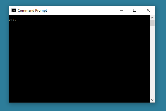
Command line interface tools are accessed on Windows PCs and laptops by searching for CMD or using the RUN feature and typing CMD in the RUN dialog box.
This opens the Command Line Interface box, which looks something like this:
Traceroute
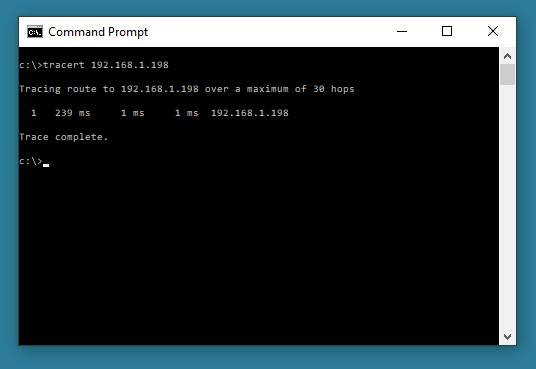
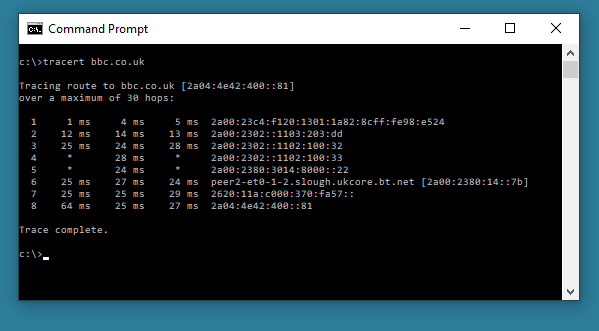
A command line troubleshooting tool that enables you to view the route to a specified host. This will show how many hops the data packets have to make and how long it takes. In Windows, the command used is “tracert”. This is of more use on larger networks. The target can either be an IPv4 or IPv6 address locally or on the internet, or a website:
tracert 192.168.1.198 (local network)
tracert BBC.co.uk (website address)
IPconfig
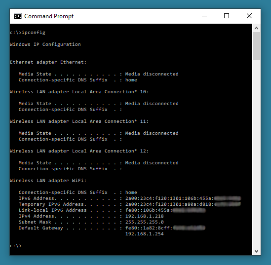
This command allows viewing of the network settings of a windows computer. The command can be used in conjunction with ‘switches’ that perform further tasks.
For example:
ipconfig – Allows you to view the allocated IP address, Subnet Mask and Default Gateway for any active network cards on the computer.
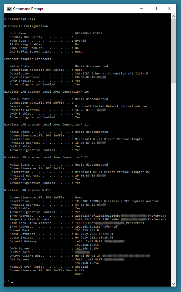
ipconfig /all - Allows you to view the allocated IP address, Subnet Mask and Default Gateway for any active network cards on the computer, plus provides further information like physical (MAC) addresses, card make and model and more details on inactive network cards
ipconfig /renew – Forces the DHCP server (if available) to renew a lease (re-issue the existing IP address for a new lease period).
ipconfig /release – Forces the release of a lease (revoke the existing IP address).
Ping
The Ping (Packet InterNet Groper) command is used to verify connections between networked devices. This is an especially useful command during the commissioning phase of a network.
The standard format for this command is: ping ip address or ping hostname.
For example:
ping 192.168.1.198 – searches for a connection from the computer you are working on to IP address 192.168.1.198 on the network (4 ping attempts).
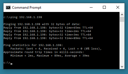
Ping hostname - searches for a connection from the computer you are working on to a device with label “hostname” on the network (4 ping attempts).
Several switches are also available with this command, the most useful ones are probably -t and -a.
ping 192.168.1.198 -t – searches for a connection from the computer you are working on to IP address 192.168.1.198 on the network (continuous ping attempts unless stopped using CTRL+C).
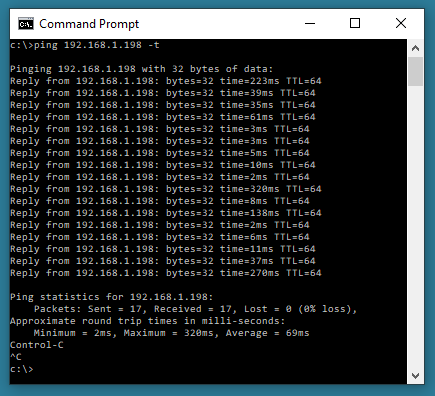
ping 192.168.1.198 -a – searches for a connection from the computer you are working on to IP address 192.168.1.198 and tries to resolve a hostname for the IP target address.
- Details
- Category: IP Networks
IP addressing, the basics explained
Classful IPv4 addressing
TCP/IP (Transmission Control Protocol/Internet Protocol) is the networking protocol of the Internet and by extension of networks in the home and office. For TCP/IP to work, your network interfaces need to be assigned IP addresses. Note that we said network interfaces and not computers. This is because IP addresses are assigned to the network interfaces within networked devices and not to computers as a whole. This means that one computer can have more than one IP address.
For example, if you have two network interface cards on your computer, then each of them can have a different IP address, either static or dynamic.
So what is an IP address?
An IP address is a number that represents a device like a network interface card uniquely on the Internet or on a local network. For IP version 4 (IPv4), this number is actually a 32 digit (32 bit) binary number, but for convenience it's normally written as four three digit decimal numbers, each in the range from 0 to 255, representing 8 digits (bits) of the binary number and known as octets. These octets are separated by dots. For instance, a typical IPv4 IP address could look something like 192.168.001.001. Leading zeros can be omitted, and so the previous address can be shown as 192.168.1.1
The four constituent numbers together represent the network that the computer is on and the computer interface itself.
Let us first look at the network address part.
On Local Area Networks like office networks, when using Static IP addresses, the IP addresses for the devices on that network will either be allocated by yourself (if it's your network) or by the IT team administering the network. Let us assume it is our own network and we have decided this will be addressed 192.168.1.0, a Class C network.
In this instance, all of the interfaces on this network would have the same network address, as in 192.168.1. and the last number, 0, will be replaced by a number from 1 to 254 for the node address (a.k.a. device address or host address). So, in this instance, the interfaces will have addresses 192.168.1.1, 192.168.1.2, and so on up to 192.168.1.254. With a Class C network we can potentially have up to 254 devices all talking happily together.
Classes of networks and corresponding IP addresses
IPv4 Classes
Depending on the size of the network, IP-based networks can be divided into three main classes. These classes represent internationally recognised standards, and as such the numbering system presented here reflects these standards.
Class A-Class A networks can be very large networks with potentially over 16.5 million devices (255x255x254) on each network. Class A networks have their network addresses from 1.0.0.0 to 126.255.255.254, with the first octet (1-126) being the network address, and the following three octets represent the node (interface) address, for example : 10.1.1.10
Class B- Class B networks are still large networks, but are smaller than Class A networks by comparison as they can only have around 65,000 devices (255x254) on each network. Network addresses for these networks range from 128.0.0.0 to 191.255.255.254. Here the first two octets are the network address and the last two octets represent the node (interface) address, for example : 172.20.1.10
b>Class C- Class C networks are the smallest as they can only have 254 devices at the maximum. Network addresses for these range from 192.0.0.0 to 223.255.255.254. Here the first three octets are the network address and the last number only represents the node (interface) address, for example : 192.168.1.10
IP addresses from 224.0.0.0 upwards to 255.255.255.254 are reserved for Class D and Class E networks, which we will not cover here.
Network 127.0.0.0 is reserved for Loopback or Localhost duties. Address 127.0.0.1 is reserved for localhost, where the computer uses it's own loopback network interface to communicate with itself. This feature is commonly used to help develop web servers and websites offline.
IP address 255.255.255.255 should not be used as it broadcasts to all devices on the local network
For a given network address, the last available address is the broadcast address for that network. For example, for the Class C network with address 192.168.1.0, the address 192.168.1.255 is the broadcast address, used to transmit to all devices in that network. So, this address (255) along with the network address itself (0) should not be used as a node address.
Now you have got the basics on IP addresses, you'll need to know a little about a closely related topic, Subnet Masks.
Introducing Subnet Masks
In an IP network, every node (interface) on the same physical network sees all of the data packets sent out on that network. As the number of nodes on a network grows, network traffic will grow many fold, bringing down performance drastically. In such a situation, you should divide your network into different subnetworks (subnets) and minimise the traffic across the different subnetworks. If required, interconnectivity between the different subnetworks would be provided by routers, which will only transmit data meant for another subnetwork across itself. The subnet mask is used to decide which parts of an IP address belong to the network and which belong to the node. To divide a given network address into two or more subnets, you can use subnet masks.
The default subnet mask for Class A networks is 255.0.0.0, for Class B is 255.255.0.0, and for Class C is 255.255.255.0, which signify a network without subnets. The ‘255’ octets signify the network address allocation, and the ‘0’ octets signify the node address allocation. These are the most commonly used subnet masks.
Which class of network to use? Which IP address?
If your network is going to be connected to the internet in any way, there is a standard to take note of with the addressing system that you use. The internet administrator - InterNIC has, via “RFC 1597 Address Allocation for Private Internets”, allocated particular blocks of network addresses for use with Local Area Networks. These IP addresses don't conflict with those of existing internet hosts and will not be allocated for use on the Internet.
The network address blocks are:
Class A: 10.0.0.0
Class B: From 172.16.0.0 to 172.31.0.0
Class C: From 192.168.0.0 to 192.168.255.0
Computers on networks using the above IP address ranges with the correct subnet masks will be treated as private ones, so you would ideally use addresses from these reserved groups only.
So which IP address class should you use for your network? The answer depends on the number of devices that are going to be connected to your network, and how they should interact. You may have several servers and workstations on the network, as well as site security devices like CCTV cameras. They may run fine together, or you may want to assign these to separate networks to split the data streams. Alternatively you could use VLANs to manage the data streams, or you could use subnet masks to manage the nodes in their own sub networks.
Subnet Masks
The subnet mask is used by the TCP/IP protocol to determine whether a device is on the local subnet or on a remote network.
In TCP/IP, the parts of the IP address that are used as the network and node addresses are not fixed, so the network and node addresses above cannot be determined unless you have more information. This information is supplied in another 32-bit binary number called a subnet mask.
In this example, the subnet mask is 255.255.255.0. It is not obvious what this number means unless you know that 255 in binary notation equals 11111111; so, the subnet mask 255.255.255.0 shown in binary, is:
11111111.11111111.11111111.0000000
Lining up the IP address and the subnet mask together, the network and node portions of the address can be separated:
11000000.10101000.01111011.10000100 - node IP address (192.168.123.132)
11111111.11111111.11111111.00000000 - Subnet mask (255.255.255.0)
The first 24 bits (the number of ones in the subnet mask) are identified as the network address, with the last 8 bits (the number of remaining zeros in the subnet mask) identified as the node address. This gives you the following:
11000000.10101000.01111011.00000000 -- Network address (192.168.123.0)
00000000.00000000.00000000.10000100 -- node address (000.000.000.132)
So now you can see, for this example using a 255.255.255.0 subnet mask, that the network address is 192.168.123.0, and the node address is 0.0.0.132. When a data packet arrives on the 192.168.123.0 subnet (from the local subnet or a remote network), and it has a destination address of 192.168.123.132, that device will receive it from the network and process it.
Almost all decimal subnet masks convert to binary numbers that are all ones on the left and all zeros on the right. Some common subnet masks are:
   Decimal                       Binary
     255.000.000.000         1111111.00000000.00000000.00000000
     255.255.000.000         1111111.11111111.00000000.00000000
     255.255.255.000         1111111.11111111.1111111.00000000
   255.255.255.192         1111111.11111111.1111111.11000000
   255.255.255.224         1111111.11111111.1111111.11100000
Internet RFC 1878 (available from http://www.internic.net) describes the valid subnets and subnet masks that can be used on TCP/IP networks.
Subnetting
As we have mentioned earlier, Class A, B, or C TCP/IP networks can be further divided, or split into subnets, by a network administrator. A network administrator who is allocating a block of IP addresses may be administering networks that are not organized in a way that easily fits these addresses. For example, you have a network with 150 nodes which you wish to divide into three networks. Each of these three networks has 50 nodes. You allocate the Class C network 192.168.123.0. This means that you could use the IP addresses 192.168.123.1 to 192.168.123.254.
With the default subnet mask applied you would be able to give IP addresses for up to 254 nodes. This works fine if all 150 nodes are on a single network. However in this case your 150 nodes are to be on three separate networks. Instead of requesting more address blocks for each network, you divide your network into subnets that enable you to use one block of addresses.
In this case, you divide your network into four subnets by using a subnet mask that makes the network address larger and the possible range of node addresses smaller. In other words, you are 'borrowing' some of the bits usually used for the device address, and are using them for the network portion of the address.
Using the subnet mask 255.255.255.192 would give you four networks of 62 nodes each. This works because in binary notation, 255.255.255.192 is the same as 1111111.11111111.1111111.11000000. The first two digits of the last octet become network addresses, so you get the additional subnetworks 00000000 (0), 01000000 (64), 10000000 (128) and 11000000 (192). In these four subnetworks, the last 6 binary digits can be used for node addresses.
Some administrators may only use two of the subnetworks when using 255.255.255.192 as a subnet mask. For more information on this topic, search the internet for RFC 1878.
Using a subnet mask of 255.255.255.192, your 192.168.123.0 network then becomes the four subnetworks:
192.168.123.0
192.168.123.64
192.168.123.128
192.168.123.192
These four subnetworks would have as valid node address ranges:
192.168.123.1-62
192.168.123.65-126
192.168.123.129-190
192.168.123.193-254
Remember, again, that binary node addresses with all ones or all zeros are invalid, so you cannot use addresses with the last octet value of 0, 63, 64, 127, 128, 191, 192, or 255.
You can see how subnetting works by looking at two node addresses, 192.168.123.71 and 192.168.123.133. If you used the default Class C subnet mask of 255.255.255.0, both addresses are on the 192.168.123.0 network. However, if you use the subnet mask of 255.255.255.192, they are on different subnetworks; 192.168.123.71 is on the 192.168.123.64 subnetwork, 192.168.123.133 is on the 192.168.123.128 subnetwork.
Default Gateways
If a TCP/IP node needs to communicate with a node on another network or subnetwork, it will usually communicate through a router. In TCP/IP terms, a router that is specified on a node, which links the node's subnet to other networks, is called a default gateway.
The following explains how TCP/IP informs a node to determine whether or not to send data packets to its default gateway to reach another node on the network.
When a node attempts to communicate with another node using TCP/IP, it performs a comparison process using the defined subnet mask and the destination IP address versus the subnet mask and its own IP address. The result of this comparison tells the node whether the destination is a local node or a remote node.
If the result of this process determines the destination to be a local node, then it will simply send the data packet on the local subnet. If the result of the comparison determines the destination to be a remote node, then it will forward the data packet to the default gateway address defined in its TCP/IP properties. It is then the responsibility of the router to forward the data packet to the correct subnet.
Troubleshooting
TCP/IP network problems are often caused by incorrect configuration of the three main entries in a node's TCP/IP properties. By understanding how errors in TCP/IP configuration affect network operations, you can solve many common TCP/IP problems.
Incorrect Subnet Mask: If a network uses a subnet mask other than the default mask for its address class, and a node is still configured with the default subnet mask for the address class, communication will fail to some nearby networks but not to distant ones. As an example, if you create four subnets (such as in the previous subnetting example) but use the subnet mask of 255.255.255.0 in your TCP/IP configuration, nodes will not be able to determine that some nodes are on different subnets than their own. When this happens, packets destined for devices on different physical networks that are part of the same Class C address will not be sent to a default gateway for delivery. A common symptom of this is when a node can communicate with nodes that are on its local network and can talk to all remote networks except those that are nearby and have the same class A, B, or C address. To fix this problem, just enter the correct subnet mask in the TCP/IP configuration for that node.
Incorrect IP Address: If you put nodes with IP addresses that should be on separate subnets on a local network with each other, they will not be able to communicate. They will try to send packets to each other through a router that will not be able to forward them correctly. A symptom of this problem is a node that can talk to devices on remote networks, but cannot communicate with some or all computers on their local network. To correct this problem, make sure all computers on the same physical network have IP addresses on the same IP subnet (if this is what is required).
Incorrect Default Gateway: A node configured with an incorrect default gateway will be able to communicate with nodes on its own network segment, but will fail to communicate with nodes on some or all remote networks. If a single physical network has more than one router, and the wrong router is configured as a default gateway, a node will be able to communicate with some remote networks, but not others. This problem is common if an organization has a router to an internal TCP/IP network and another router connected to the Internet.
Static IP addresses versus Dynamic IP addresses
In assigning IP addresses to nodes, you have two choices. You can either go around typing in the individual address on each node (static IP addressing) or you can set up one node to assign IP addresses to the others (dynamic IP addressing). For typical IP CCTV and IP access control networks, Static IP addressing is the preferred route, since a loss of power event on a unit does not cause it's IP address to change. Dynamic addressing is sometimes used on “plug and play” IP CCTV systems, but these systems usually incorporate software to keep track of a device using Its physical (MAC) address.
In a computing environment, dynamic IP (DHCP) addressing may be preferred for three reasons. First, it makes the job of administering the network such as adding new devices, avoiding IP clashes, etc a lot easier. And second, since only those machines that are switched on will need an IP address, you could potentially have more machines on your network with dynamic addressing than you could with static addressing. Finally, mobile computing has become an everyday reality, and notebook computers have a likelihood of moving from one network to another or from one subnet to another. In such a situation, if you have static IP addressing, you have to reconfigure the machine every time you move it - something that is eminently avoidable. So the benefits to these types of networks are obvious.
Dynamic addressing uses DHCP (Dynamic Host Configuration Protocol) to allocate nodes with addresses automatically. To make DHCP work on your network you have to set up a DHCP server.
The good news is that network admins can have both addressing systems running on their network together, as long as they reserve the static IP address ranges on the DHCP server.
- Details
- Category: IP Networks
Network Cabling
Network cabling (a.k.a. structured cabling) nowadays is generally wired using Category 5e (low speed), Category 6, Category 6A, Category 7 or maybe even Category 8 (high speed) cables, depending on the required design and expected traffic. These cables usually flow through the building on supported containment like cable basket or cable tray from the comms cabinet out to the network sockets, one cable for each socket port required. Usually extra sockets over and above the bare minimum required are fitted, (known as flood wiring) since it is more cost effective to install more than you really need at the outset than come back to install more later.
So what is a Category whatever cable?
Anyone who has plugged their computer into a network or broadband Internet connection such as cable or ADSL, has used an Ethernet cable for this. Ethernet cables are the standard cables commonly used to connect a modem to a router or network, and likewise, to connect a network switch or hub to a computer's network interface card (NIC).
Not all Ethernet cables are created equal. Ethernet cable technology has been evolving since the beginning of the Ethernet standard back in 1985. Many different categories of Ethernet cable have been developed, and each category has different specifications as far as shielding from electromagnetic interference, data transmission speed, and the possible bandwidth frequency range required to achieve that speed. Some confusion can arise when looking at all of the available options for Ethernet cabling. The standard gauge sizes (AWG) are also different in the different categories of cable, and this can influence the end results for both quality and speed. Luckily, the category of cable is usually clearly printed on the cable's sheath, so there can be no doubt as to the type of cable being used for existing networks if you are adding to it. There are also certain types of cables recognized as common industry standards. Described below are a few of the most common categories of Ethernet cable that are used in networks today. We are not going to look at the obsolete types, so for this reason we will jump straight to Category 5e Cable.
The major categories of Ethernet cables
Category 5e
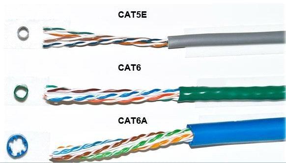
The Category 5 enhanced (Cat 5e) is typically installed as an Unshielded Twisted Pair (UTP) cable and is an improved version of Cat 5 cable, which is optimised to reduce crosstalk, or the unwanted transmission of signals between data channels. This category works for 10/100 Mbps and to a lesser degree, 1,000 Mbps (Gigabit) Ethernet. Bandwidth is also increased with Cat 5e cables, which can support a maximum bandwidth of 100 MHz. Cat 5e cables are backward-compatible with Cat 5 cables. Small Category 5e networks are still being installed today, however many customers have moved up to Cat 6 or Cat 6A cabling.
Category 6
One of the major differences between Category 5e and the newer Category 6 (Cat 6) is in transmission performance. While Cat 5e cables can handle Gigabit Ethernet speeds, Cat 6 cables are certified to handle Gigabit Ethernet with a bandwidth of up to 250 MHz. Cat 6 cables have several improvements, including better insulation. These improvements provide a higher signal-to-noise ratio, and are better suited for environments in which there may be higher electromagnetic interference. Some Cat 6 cables are available in duct grade (ruggedised) sheath, shielded twisted pair (STP) forms or unshielded twisted pair (UTP) forms. Cat 6 cable is also backward-compatible with Cat 5 and cat 5e cables. Cat 6 cables are slightly more complex to terminate, due the central core of insulation around which the wire pairs are wound.
Category 6A
Category 6A cable, or Augmented Category 6 cable, improves upon the basic Cat 6 cable by allowing 10,000 Mbps data transmission rates and effectively doubling the maximum bandwidth to 500 MHz. Category 6a cables are available in UTP or STP form and require specific Cat 6A Plugs for termination, STP versions must have specialised connectors that ground the screen/ drain to a metal shield. With each successive category, there has been an increase in data transmission speed and bandwidth. This cable is best installed using patch panels, data network sockets and patch leads rather than crimping plugs on each end.
Category 7
Category 7 cable is a stiffer cable which is slightly more difficult to install than Cat 6A. It is slowly being added to the specs for higher traffic networks and new installs, which will in turn bring prices down and allow wider adoption.
Category 8
Category 8 cable is the current high budget solution for maximum bandwidth. For this reason and others the cable has not yet seen high levels of adoption.
When installing a new network cabling installation, the highest cable categories are recommended, but only if all of the other equipment on the network is capable of similar speeds. Otherwise, expensive cables are only as fast as the slowest piece of hardware on the network.
Other qualities of Ethernet cables to consider
There are a few important considerations that apply to all Ethernet cables. Data transmission rate and bandwidth both decrease as the cable length increases, so the shorter the cable length, the better. For 10/100/1000BASE-T networks, or those that have maximum speeds of 10, 100, or 1000 Mbps, including all the aforementioned cable types, 100 meters is the maximum allowable cable length before the signal degrades unacceptably. Usually this is stated as 90 metres, to allow up to 10 metres for patch leads. For category 6A cables running at 10 Gbps speeds, 55 meters is the maximum allowable length, and even this length is only available in low interference environments.
Ethernet cable connectors
The ends of Ethernet cables that connect into a computer Network Interface Card (NIC), router, or other network device are known by several names. Jack, modular connector or plug are the most commonly used terms. Ethernet cables can be purchased in many lengths, up to 500 metres. Short lengths of Ethernet cable are usually sold with the connectors already installed (known as patch leads), but for custom installations requiring non-standard lengths, cable is often sold in bulk quantities, and connectors must be installed on the ends.
The most common type of connector for Ethernet installations is referred to as an "RJ-45" connector. It is officially known as an ‘8P8C’ connector, but this term is rarely used in the field, and the term "RJ-45," which was the telephone industry's term for this connector's wiring pattern, has become the customary colloquial name for the connector itself. Categories 3 to 6 all use similar versions of the RJ-45 connector, but Cat 6A and Cat 7 use different versions of the connector.
RJ-45 pin assignment
There are two industry standard pin assignment configurations for RJ-45 connectors: T568A and T568B.
The T568B standard is the most used standard, but T568A type connections are by no means obsolete.
In every case, the specifications of the cable, such as its category, whether or not it is shielded, and whether or not it needs to be grounded, must match the specifications of the connector.
Of course patch leads are widely manufactured, and leads of several lengths and colours are available quite cheaply. Even for a single lead, buying a pre-made one is likely to be the most cost-effective route. But what if you need to make your own lead?
Here's what you'll need to source:
A length of cable
If you are using cable measured and cut from a reel (rather than having a whole box or reel to hand), always allow yourself some extra cable to cover for any initial termination mistakes you might make. For longer lead lengths that may be linking rooms or levels in a building, keep the cable away from mains wiring, pipes or vents, and sharp edges.
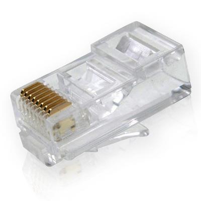
RJ-45 plugs
These are readily available from blister packs of 10 up to boxes of 500. You will need two for each patch lead, but spares are always handy. Make sure you buy the correct version of the plug to match the cable you have.
RJ-45 crimp tool
These are used to cut and strip the cable, as well as 'crimp' (squash) the brass plug terminations and strain relief clamp of the plug onto the cable.
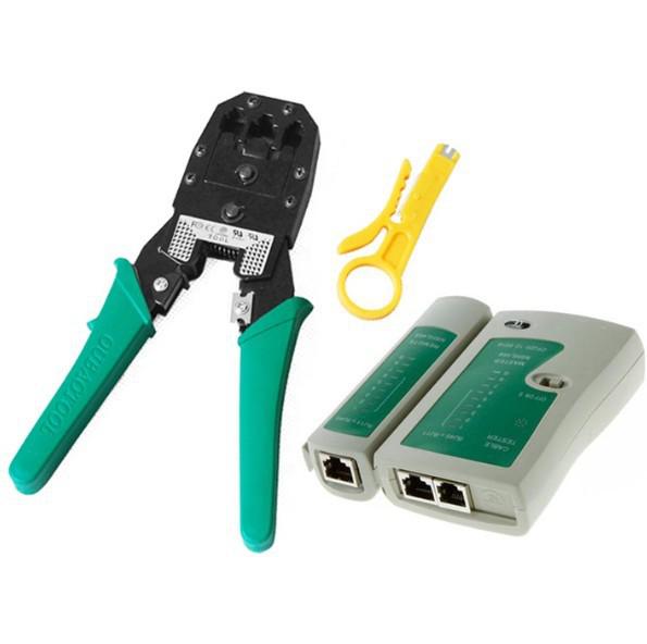
Crimp tool, Cable stripper and lead tester
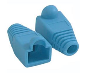
RJ-45 plug boots
An optional item that you might consider, especially if you plan to plug/unplug the patch lead often, as the plug boot helps to take some of the flexing strain from the cable as it enters the plug.
Cat 5 cable stripper
A handy tool though only really necessary if you plan to make lots of leads, the stripper tool cuts into the cable jacket to the correct depth, leaving the wires underneath undamaged.
Wire cutters and craft knife
Wire cutters are handy for cutting the cable and wires to the correct depth. You can (if you are very careful) use a craft knife to remove the cable jacket.
Lead tester tool
A useful device which helps to prove your patch leads are correctly terminated.
Making your own patch leads
For Cat 5e cables, find the end of the cable and push on a RJ-45 boot, circular end first (if you are using them) then strip between 25 - 50mm of outer cable jacket from the cable. To do this, either ring around the jacket (being careful not to damage the inner conducting wires), gently with a craft knife and pull off, or use a UTP cable stripping tool. Once you have done this, you will have exposed the cable wire pairs, like this:
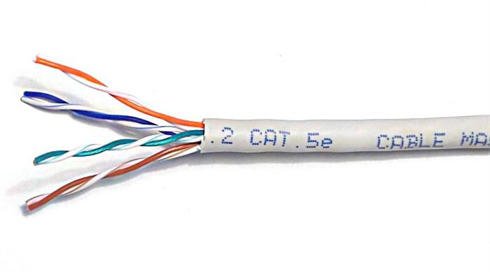
Separate the four twisted wire pairs from each other, and then unwind each pair, so that you end up with 8 individual wires. Straighten and flatten the wires out as much as possible, since they'll need to be very straight for proper insertion into the RJ-45 connector.
I find that if I have stripped off a slightly longer length of the outer cable jacket than is strictly necessary, that unwinding the pairs and straightening them out is less fiddly. You can always cut the excess wire off.
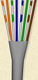
Once you have done this, hold the cable with the wire ends facing away from you. From left to right, arrange the wires in a flat, side-by-side ribbon formation, placing them in the following order: white/orange, solid orange, white/green, solid blue, white/blue, solid green, white/brown, solid brown. (see picture below)
Hold an RJ-45 plug beside the cable. The end of the cable jacket should line up with the step, which is about a third of the way along the plug, and the wires must be long enough to reach to the far end of the plug. If the wires are too long, trim them back, making sure that you cut the wires square across the 'ribbon' you have made out of the individual wires.
Holding the RJ-45 connector so that its brass coloured pins are on top of the plug at the far end, and the plug-clip side is facing down, carefully insert the flattened, arranged wires into the connector, pushing until all of the wire ends stop in the far end of the plug. Note that this will not happen if you have not previously cut the wires 'square', or if you have cut them too short. For strength of connection, also make sure that the cable jacket fits as far as possible into the connector. The cable/plug assembly should now look like this:
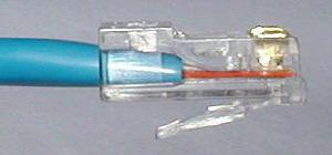
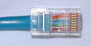
Check to make sure that the wire ends are touching the end of the plug, and that the wires have aligned into the plug in the correct order. If they are not, remove the cable from the plug, re-arrange the wires into the proper order, and re-insert. Remember that once the RJ-45 plug is crimped onto the cable, it's permanent. If you realise that a mistake has been made in the wire order, or that one of the wires is too short after you have crimped the plug, you'll have to cut the plug off and start over - now with a slightly shorter bit of cable.
Okay. So having double checked the wires are in the correct order etc, and the cable jacket is fully inserted, fit the prepared plug/cable assembly into the RJ-45 slot in your crimping tool. Firmly squeeze the crimper's handles together until you can't go any further. Release the handles and repeat this step to ensure a proper crimp.
Now push up the cable boot (if you fitted one) to cover the back end of the plug, measure off the cable you need for your lead, and cut to length.
Repeat the cable termination process with the other end of the cable. Once you have done this, you are free to test your new patch lead with a test unit. All being well with this, you can then plug-in and use the lead.
Remember to label the cable ends with a meaningful ID so you know what it is for.
The Colour Standards
TIA/EIA-568 is a set of telecommunications standards from the Telecommunications Industry Association (TIA), an offshoot of the Electronic Industries Alliance (EIA). The standards address commercial building cabling for telecommunications products and services, e.g computer networks. Perhaps the best known features of TIA/EIA-568 are the pin/pair assignments for eight-conductor 100-ohm balanced twisted pair cabling, known as Ethernet. These assignments are named T568A and T568B. You can use either version of the colour standards without detriment, as long as you stay to the same standard throughout your install. Below is a picture of how the colour standards differ inside a RJ-45 plug.
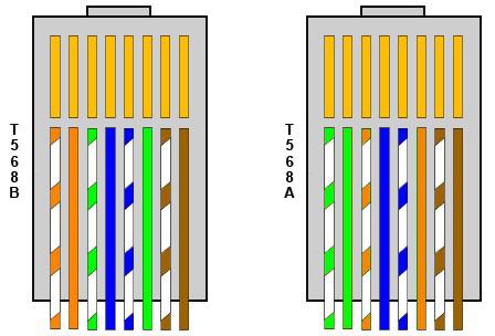
You'll notice from the drawing above that we previously described the making of a lead to the T568B standard, with both ends having this colour layout. However occasionally a 'crossover lead' is required (this is getting rarer).
If you need to make a crossover patch lead, simply make one end of the lead to T568A standard, and one end of the lead to T568B standard.
Do’s and Don’t’s of installing network cabling
Here are some common issues that can drastically affect network performance.
Do Keep the cable well away from mains wiring, hot pipes or heat vents, and sharp edges.
Don’t Kink, fold or twist the cable during install. This squashes the wires inside the cable and can upset the twist ratio and displace the wire insulation inside the cable, which can cause short circuits. The twist ratio is important for maintaining network speeds. Damaged cables immediately provide poorer performance or failure.
Do Use velcro straps to secure Cat 6/6a/7 cables on tray or basket runs, as cable ties can squash the cable including the central air gap, which badly degrades network performance. Cable ties where absolutely necessary should be kept to a minimum and be as loose as can be tolerated for a quality install.
Don’t Bend the cables sharply around corners. This is why most dado or compartment trunking systems have sweeping bends. This applies as much to mains cables as it does to networks. Network cables should not be jammed together into the smallest mini-trunking possible and subjected to sharp right angle bends. If this is your only option, it will definitely provide slower network speeds.
Do keep your cable runs as short as possible whilst still providing a neat finish. Cable runs should ideally be less than 90 metres, and on no account be more than 100 metres in total, including patch leads.
Don’t strip and untwist any more of a cable than is absolutely necessary to terminate it correctly. This again affects the twist ratio on the cable which will adversely affect network speed.
Do Terminate cables using the correct IDC punch down tools or crimpers. Don't be tempted to use other tools for this, you might get it to work, but at the cost of network speed.
Don’t install cables in a spider web configuration, always try to keep network cables to contained routes and ensure they are neatly installed and secure. Cables should be neatly loomed into comms cabinets or hub points where provided.
