- Details
- Category: Intruder Alarms
Passive Infra-Red (PIR) movement detection.
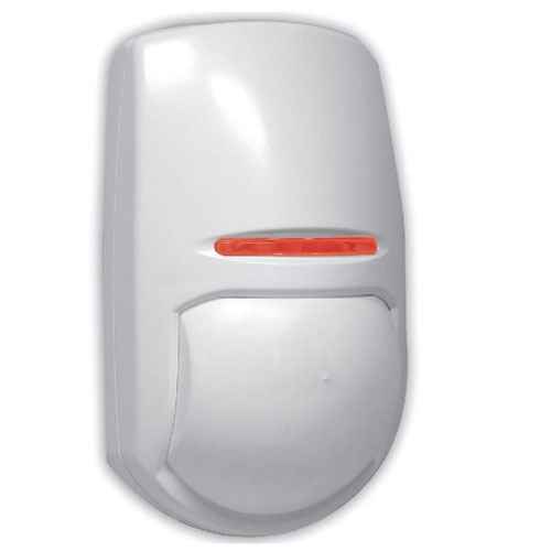
The PIR detector is an area intrusion detection device which is used in most modern intruder alarm installations to some degree. PIR detectors are triggered by heat and movement.
The PIR is passive in the sense that it only receives infra-red energy and is not a transmitter.
The PIR unit detects via many infra-red detection areas spread via the detector's Fresnel lens into a wide pattern usually covering 90 degrees or more.
These detection areas attempt to detect changes in temperature.
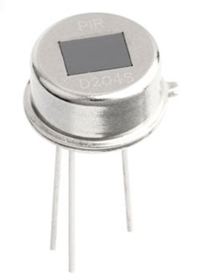
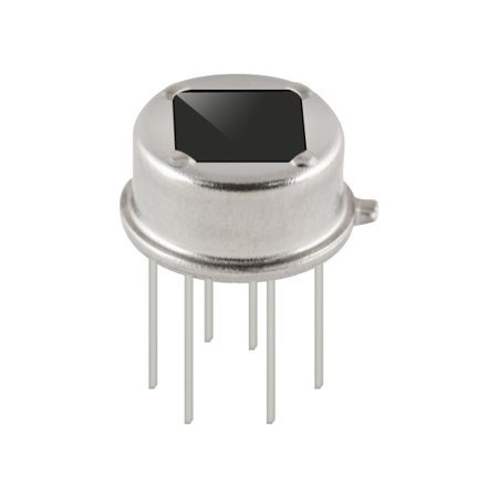
The PIR does this by using a sensor device called a pyro. The pyro device is made up of two sensing elements that compare amounts of infra-red radiation received.
When the sensor is idle, both elements detect the same amount of infra-red radiation - which is the ambient amount radiated within the detection area.
When a warm body like a human or animal passes by, it first triggers one pyro element, which causes a positive differential change between the two halves.
When the warm body leaves the sensing area, the reverse happens, whereby the sensor generates a negative differential change.
These change pulses are what is detected.
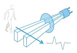
Therefore a PIR device's sensitivity can be adjusted by changing it's pulse count setting.
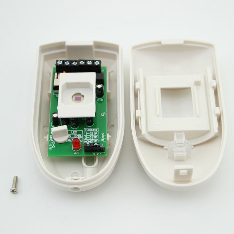
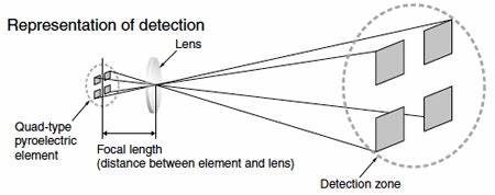
The Fresnel Lens on the PIR allows for multiple detection areas for the pyro sensor elements, all angled in a set pattern to cover the area.
Since the PIR detector will be much more reactive if the detection areas are crossed, it is better to site these detectors where a potential intruder is likely to walk across the path of detection, rather than walk between the detection areas.
This is one reason that wall mounted versions are usually fitted in the corner of a room, since the best coverage can be achieved from a corner. Check out this drawing below:

We can see above that a standard wide angle wall mounted unit has many detection areas. These detectors are available with differing detection ranges.
The most popular models for internal use are usually 12 or 15 metre range devices.
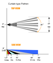
Curtain lenses are available that provide a narrow coverage area:
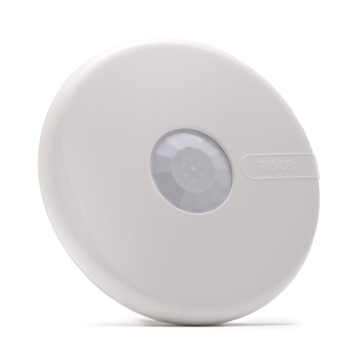
Ceiling mounted PIR detectors provide a 360 degree coverage up to –mtrs.
Quad PIR
Quad Element PIR detectors are equipped with a quad element pyro package, which is essentially two pyro devices which compare against each other to help filter out false alarms.
Dual Technology Detectors (Dualtec/ Dualtech)
Dual technology detectors combine two differing technologies to help filter out false alarms in challenging environments - the most common versions combine PIR detection with microwave detection technology, although PIR with ultrasonic detection versions are available.
Dual technology detectors operate as two separate detectors, each detecting movement and IR.
With a dual passive infra-red / microwave detector, if the microwave unit activates, the detector waits for given period of time to determine if the passive infra-red unit also alarms.
If so, an alarm activation signal is sent but if not, the detector resets. Both detectors must activate within a prescribed time window for an alarm signal to be generated.
As these detectors are using both active and passive detection principles, false alarm problems are reduced.
This is because the environmental causes of false alarms for the active detectors are different from those for the passive detector.
What activates a microwave or ultrasonic detector would not affect a passive infra-red.
The two technologies have differing coverage patterns and in the case of microwaves the detection can pass through some materials.
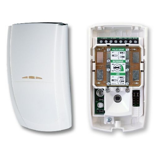
In the picture below the microwave detection is located just underneath the connection terminals, with the PIR pyro element below that.
TMD (Twin Movement Detector)
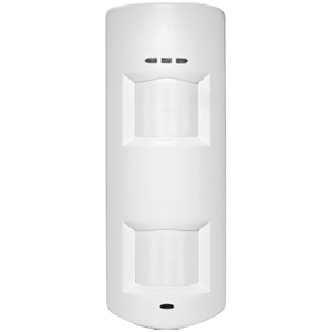
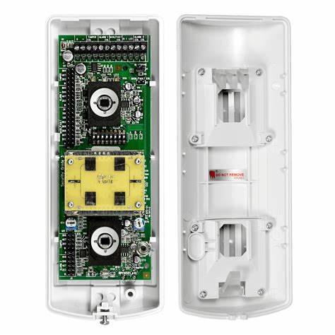
This is two individual PIR detectors in one housing (one dual technology, one not), usually with differing coverage patterns for maximum detection.
The detectors have separate zones on the intruder alarm system to allow for signalling of a confirmed intruder detection activation from a single device.
Tip:
Try not to aim the PIR straight at a window as car headlights and direct sunshine can set them off. Don't place the PIR where it will directly view an open fire.
Don't fit it above a radiator, as the rising heat currents can trigger the unit also.
In summary:
The PIR receives far infra red energy. Has a detection pattern which is divided into elements in order to measure changes in temperature.
The Quad PIR is able to filter out false alarm causes more effectively than a standard unit with dual pyro elements.
There are essentially two different types - corner mounted or ceiling mounted.
Corner mounted types have a 90° volumetric range in the order of 12-15 metres when at a height of 2.3 m.
Ceiling mounted types have a 360° range in the order of 12-15 metres. They should only be attached to secure ceiling surfaces.
Hazards/false alarm sources
The PIR can be affected by:
Heat sources, Fires
Sunshine through windows,
Fast changing climatic conditions
Unstable power supplies
Insecure fixing of the detector or cover
Tools required to fit:
1. No.2 pozidrive or philips for fixing screws (usually 1 1/2x8 countersunk)
2. 3mm flat blade screwdriver for connection of terminals
3. a drill with a 5.5mm masonry bit may be required depending on mounting materials, where used, rawlplugs will also be needed.
- Details
- Category: Intruder Alarms
Batteries are typically used within the system control panel and other auxiliary power supplies connected to the system as a secondary (backup) power source should the mains supply fail.
There are minimum operation durations set in both BS 4737 and the newer BS EN 50131 standards that cover their use. there are also guidelines for replacement of the batteries covered by these standards and also inspectorate Codes of Practice.
The backup battery
The backup battery is a vital component of any intruder alarm system, working 24/7 in the background to help keep the system running. It is however a common cause of the dreaded 3am call-out for alarm companies. For systems with maintenance contracts it is often due to premature battery failure from environmental causes (batteries don't like heat or water). For systems without maintenance contracts, this is because it is also the most overlooked part of the system as it is cooped up inside the control panel or remote power supply. So it remains out of sight and very much out of mind. That is, until it fails and causes the system to alarm.
The batteries used in the control panel are a sealed lead-acid (SLA) rechargeable type - so you need to get the correct voltage and amperage rating i.e. 1.2 or 2.1 or 3.2 or 7.0 amp-hours (Ah) etc, that suits the control panel and system requirements.
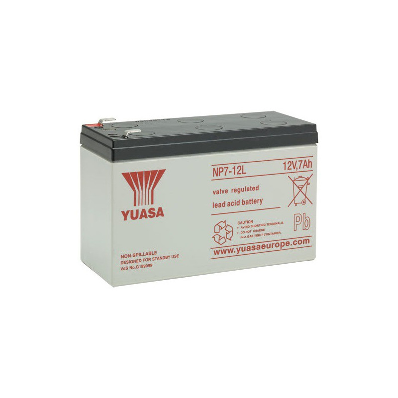
Standard SLA battery sizes
The most popular battery sizes rated in ampere hours at 12 volts are:
1.2 Ah
1.9 or 2.1 Ah - slim form with terminal on top at each end.
2.8 or 3.2 Ah
7.0 Ah
12.0 Ah
17 Ah
Larger sizes are available. Picture on right shows 7Ah unit
SAFETY WARNING
These types of batteries can be dangerous: Please store carefully with the terminals covered. Shorting out a battery can cause it to overheat, expand, blow off excess pressure, smoke and sometimes - catch fire. Many tales have been told of fires or nearly fires with shorting batteries. Only stock the batteries you need and ensure they are safely stowed and protected from shorts. When fitting or replacing new batteries take the plastic covers from the new battery terminals, label and date the battery and fit it. When you replace the battery, do not throw the old one in the bin. Instead fit the plastic covers from the new battery on to the old one, tape them in place and return it to your local recycling facility. Make sure when transporting batteries that they cannot be shorted out by other batteries, stray tools or metal parts.
- Details
- Category: Intruder Alarms
Battery ratings and replacement schedules
Sealed lead-acid batteries of the type that are used in fire and security system applications are rated for voltage and current output. Whilst these batteries are usually supplied in a 12 volt configuration, they are supplied with many different Amp-hour ratings, which usually have an effect on the physical size and weight of the batteries.
Amp-hour ratings
Let's say in theory that a 12 volt, 7 Amp-hour rated battery will give you roughly 7 amps at 12 volts for one hour, or 1 amp at 12 volts for 7 hours.
Let's apply that theory to an intruder alarm, and let's say the total load of the intruder system was 500mA (0.5 amps) - that means in theory that we should get 14 hours of battery power from the 7Ah battery. This is great on paper, but it does not always work in practice, because new batteries do not always provide the advertised rating, and as batteries get older, they naturally decay and become less efficient. How you store the battery during it’s lifecycle also affects how fast it decays.
These points have been taken into account with the industry battery testing procedures and standard calculations which can be employed to determine what size of battery is actually required. In some of the cheaper domestic intruder alarm systems it is quite often the case that the battery choice is determined by the size of the panel physically. You hope that the battery size that fits is sufficient and that the maximum current draw for the system has been taken into account when the panel was designed. However it is still up to the installer to verify that the battery fitted is adequate to meet the system's requirements.

Installing a battery
The first thing to do when installing a battery is to always fit a battery label on it and put the install date and the other necessary details asked for on there. This is your chance to verify that the battery you bought supplies what it is supposed to. The main reason for adding a label is to record the rate of degradation each time it is tested. The fact is that a battery will last about five years* on average, hence why you should change it every five years maximum, even if the battery is still ‘good’ on year five. If you do not change the battery regularly, it will eventually provide a 3 am call out, because the failure rate on SLA batteries after five years gets pretty steep. This makes it important to know when the battery was installed, and if it has been regularly checked. This is what the battery label is all about.
So where do we get this five year maximum figure from? Well, a few places - The old UK BS 4737 standard stated that when the battery gets to 80% efficiency (how it holds its charge), it should be changed. Also most manufacturers will tell you that their batteries will, if stored at the right temperature, get to 80% efficiency after 5 years.
* The industry inspection bodies, such as NSI and SSAIB have a code of practice which calls for a four year change over policy, if the battery has not already failed a load test. The reason for this is that the battery’s life could be shortened if it is stored at relatively high temperatures - for instance, if the intruder panel was installed in a hot cupboard. In that case, because of the heat the battery might get to 80% efficiency after just 3 years. Hence it is best practice to fit the battery with a label, put the install date on it, and check and record it’s performance annually. Any signs of failure should result in the battery being replaced.
So why the fixation on failing batteries? Well, apart from the much higher risk of faults on the system appearing, the control panel doubles up as the battery charger. Sometimes when a battery fails, it can damage the charger circuit in the control panel. So instead of just having to fit a replacement battery you might have to replace the control panel as well. An expensive lesson. Poorly maintained intruder alarm systems can also be anti-social - for example if you get a power cut in your area and a couple of alarms immediately begin sounding, it’s because their control panel batteries are faulty - and after an hour another couple will join in and so on. This causes noise nuisance and call-outs. However alarms with healthy batteries should be ok for many hours.
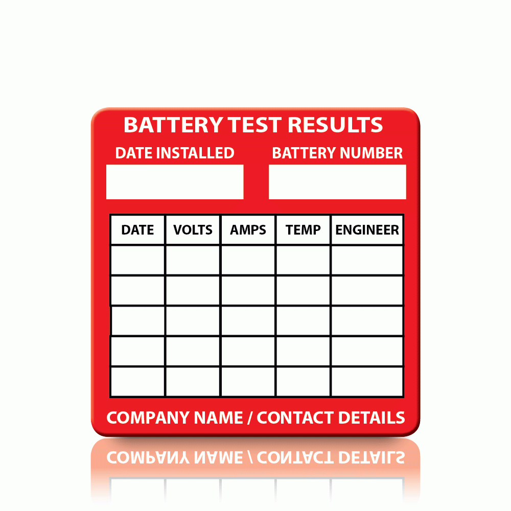
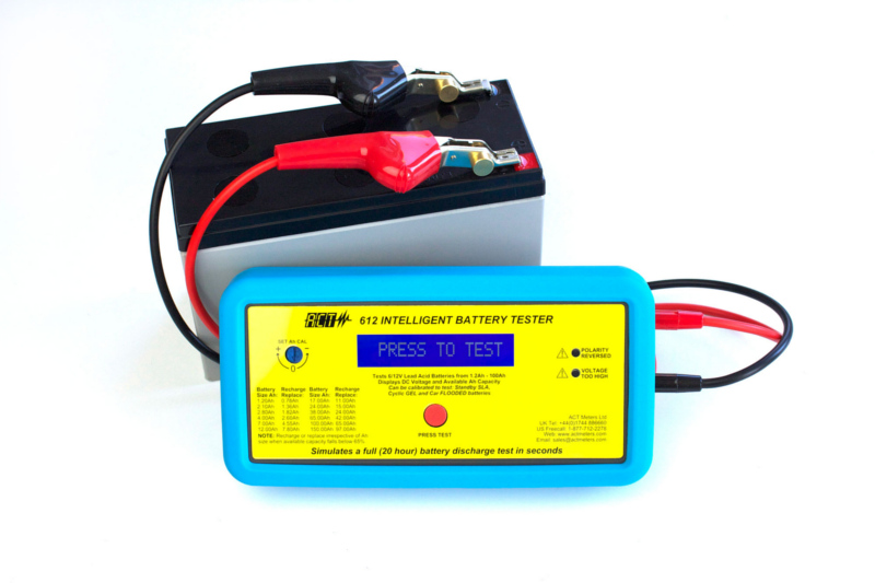
So how do you know if a battery is failing? The very first line of defence is the install date you put on that battery label. The next, and only slightly more technical step is to use a calibrated battery test meter. These units give you a display of how much life is still in the battery, it’s temperature, voltage output etc. The results of any battery test should be recorded on the battery label and in the system log book.
Safety Warning
These types of batteries can be dangerous if installed or stored improperly, which can be a fire risk. Ensure that the battery terminals are insulated when in storage from short circuits and return any end of life batteries to your local recycling facility. Make sure when transporting batteries that they cannot be shorted out by other batteries, stray tools or metal parts.
The safe use, storage, handling and disposal of new and used batteries is an industry inspectorate audit point.
Calculating the correct battery size
Intruder alarms:
The old UK BS 4737 standard stated that a control panel battery should maintain the system for a minimum of 8 hours. It’s newer replacement, BS EN 50131 and PD 6662, calls for a 12 hour period for Grade 1 and Grade 2 systems, and a 24 hour period for Grade 3 and Grade 4 systems. So you need to ensure you fit a battery or batteries to meet these requirements. The good news is that there are measurements you can take and calculations you can do to verify that you meet the BS EN 50131 requirements.
Let’s look at the BS EN 50131 requirement (since it’s the one we should be using for new systems). This recommends that the battery should maintain the alarm system in standby (unset) mode for 12 hours (Grades 1 and 2) or 24 hours (Grades 3 and 4).
To determine the battery size required for the system, the current (in milliamps or amps) used by the system in standby mode should be calculated (at the design stage) and measured (verified on site) and then this figure multiplied by 12 or 24 (hours). The resulting figure should then be multiplied by 1.25 (battery efficiency de-rating factor) to give the minimum size of battery required.
For example, consider the following Grade 1 system with typical standby currents.
Control Panel (integral keypad) = 80mA
External Sounder = 35mA
4 x PIRs (11mA each) 4 x 11mA = 44mA
Total system current (standby) = 159mA
Battery required for 12 hours standby = 12 hours x 159mA = 1,908mAh = 1.9Ah
Add the de-rating factor for battery efficiency loss = 1,908mAh x 1.25 = 2.442mAh = 2.44 Ah minimum required capacity.
Hence a 2.8 Ah battery (the next closest battery size up) will suffice.
Obviously, the addition of extra powered detectors or external sounders could then require a larger battery, so these calculations and measurements should be re-done if additions are made.
So how did we get these numbers? The numbers quoted for the control panel, external sounder and PIRs were all taken from the respective installation manuals and specification sheets, which would form the basis of the design calculations. To verify the design calculations and measure the real-life values, we need to use our multimeter to measure the actual system standby current value.
Here’s How:
Once the system is powered up and complete, and with the control panel in engineer mode and the panel lid removed, switch on and set up your multimeter to measure current (Amps).
Now take the red (+) battery lead from the battery and attach it securely to one of your multimeter leads.
The other multimeter lead should now connect with the red (+) battery terminal.
Now turn off the mains power to the panel.
The alarm system should still be running on battery power, through your multimeter, which will be reading the total system standby current.
Take note of the measurement figure from your meter.
To comply with NSI codes of practice you will also need to measure and record the system alarm current.
To do this, trigger the alarm so that all sounders and strobes are in operation and measure the current drawn.
Take note of the measurement figure from your meter and turn on mains power.
Remove your multimeter and reconnect the battery lead to the battery, refit the panel lid.
Any values gleaned should be noted on the system paperwork and run through the battery calculation above.
Please note: There is a slightly different and more involved calculation for fire alarm systems which we will cover in a separate article.
- Details
- Category: Intruder Alarms
The Intruder Alarm (a.k.a. Burglar Alarm) has been with us for many years now - probably much longer than you might think. The basic concept of an intruder alarm is to cause an alert of some sort to be triggered when a property is breached by an intruder. As you can imagine this is not a new concept and in fact it is a long-standing duty carried out by Guard Dogs, Guard Geese, and of course, Guards. But back in the early 1700’s a mechanical intruder alarm was first produced.
Mr Tildesley, an English inventor, had an idea to connect a set of chimes mechanically to a door lock. The inventor’s advertisement proclaimed: “The bells associated with it are constructed in such a manner that no sooner is the skeleton key of an intruder applied to the lock than the bells begin to chime a plaintive air that inspires such sentiment in the minds of the housebreaker that will doubtlessly prompt him to take precipitous flight.” This idea of causing an intruder to panic and flee remains a central aim of the modern electronic intruder alarm system.
The move to Electricity
In the early 1850’s Augustus Russell Pope, a U.S. inventor from Boston, discovered how to use electricity, magnets, and a bell to create an early electrical version of the modern intruder alarm. His battery operated alarm unit could be used on a window or a door. If the window or door was opened, the circuit would be completed, causing the bell to ring. The bell was mounted on top of the door frame or window opening and fixed into the wall. Wires ran from a spring ‘key’ in the door/window through an electromagnetic relay of sorts near the bell, allowing the current to run constantly once the door/window tripped the spring. The special feature of Pope’s invention was that the alarm could not be switched off by merely closing the windows or doors (the spring switch had to be reset).
However despite the pioneering work of Pope, most people usually assume that someone else was the father of the modern electric alarm system. Namely Edwin Holmes. He was a businessman and founder of the first installation company for electrical intruder alarm systems, who bought the rights to Pope’s invention in 1857. It was he that then led the way in the business of electro-magnetic alarm technology with his “Holmes Electric Protection Company”.
On October 11, 1859, George F. Milliken was issued U.S. patent number 25,753 for improvements he made to the electric intruder alarm. He designed the alarm device to reside in the room where the homeowner slept or would be unaware of potential thieves forcing entry. This design allowed for wire runs from all windows and doors, where each door/window had a spring with a certain amount of creases that signified a specific number of rings on the alarm bell, alerting the homeowner of the precise door/window where entry had occurred. This improvement on the original system forms the basic idea behind ‘zones’ on a modern electronic intruder alarm system.
In 1868 improvements were again made to the electric intruder alarm. Holmes began offering a system with a clock that would automatically turn the alarm on and off. Visually zoned systems were introduced and were often housed in ornate wooden boxes along with the alarm bell. He also began to offer alarm systems with telephone links.
In 1905 The American Telephone and Telegraph (AT&T) Company bought the Holmes business and linked it to their own emergency call systems for police and fire fighting personnel, taking the electric intruder alarm to another level.
Electric Intruder Alarms were first introduced to the UK by Thomas Gunn Limited, who began installing electric intruder alarms in London in 1907. It was considered a specialist trade for many years, over time evolving from electric systems to electronic equivalents, until the 1970s when the invention of the Passive Infra-Red (PIR) detector opened the sector up to a wider range of installers.
- Details
- Category: Intruder Alarms
Many people ask about a 'standard' colour code for intruder alarms. The fact is that this has never been a part of any standard and each company has their own preferred colour code scheme.
On a fully-wired Intruder Alarm System, alarm cable generally forms the links between all of the devices 'in the field' and the control panel or zone expander. In the UK, the cable itself should conform to BS 4737 Part 3, which still applies to alarm cables and components.
You should always use the correct cable for the job - never use telephone cable or Category 5 or 6 cable for alarm system device wiring, since these cables contain solid-core wires which are much more liable to breakage at the screw terminal connections. This is why these cable types are usually terminated using Insulation Displacement Connectors (IDC).
Alarm cable colours and 'colour codes'
First of all, we should explore the standard wire colours available in the three most popular alarm cable variants:
4-core = Red, Black, Yellow, Blue
6-core = Red, Black, Yellow, Blue, White, Green
8-core = Red, Black, Yellow, Blue, White, Green, Orange, Brown
Using a 'colour code'
Let us examine a typical colour code scheme and the (usually historical) reasons behind it.
Every alarm cable has a Yellow wire and a Blue wire, and these are used for the zone circuit.
Red and Black is for DC power, i.e. 12 volts DC from the control panel, as this matches up with the battery + (red) and - (black) lead colours.
White and Green is the for the tamper circuit.
Working with the colour code above then, a BS EN 50131 Grade 1 magnetic door contact needs a zone circuit pair (Yellow/Blue) and a tamper circuit pair (White/Green). To stick to the colour code, we would use a 6-core cable and tuck away the spare Red and Black wires for future use.
A PIR movement sensor needs a zone circuit pair (Yellow/Blue), a tamper circuit pair (White/Green) and a DC power pair (Red/Black). While a 6-core cable would be perfectly adequate, we would recommend using an 8-core cable and tucking away the Orange and Brown wires for future use.
If you stick to this code, when you connect it up you can tell at a glance that all of your DC power wiring is Red / Black, zone wiring is Yellow / Blue and all of your tamper wiring is White / Green.
This should make the whole system easier to connect and repair.
TIP:
When you are preparing the cables at the control panel it is good practice to twist the circuit pairs of a cable before running them neatly to their connections and terminating. Any spare wires should be loomed and safely secured for future use. Individual cables should be clearly marked as to their use, i.e. dining room PIR, Front Door, etc. for ease of maintenance and future fault-finding.

