UK telephone systems were originally installed in fixed locations in the home via line terminal boxes like the one below, installed by Post Office telephone engineers. The boxes at the telephone location were usually colour coded to the telephone supplied - you had to specify the colour when ordering the line, at this time all phones etc. were exclusively supplied by the supplier, this was Post Office Telephones (until 1969) or Post Office Telecommunications (1969-1980). The terminal boxes were usually marked GPO, signifying 'General Post Office' property.
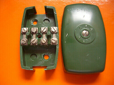
This led to quaint furniture items such as the telephone seat or bench, comprising a place to sit at the telephone location with a shelf for the phone and a shelf or drawer for the telephone directory.
Everything in the home was rented to the subscriber, including the line cabling and telephone itself. Eventually it was agreed that subscribers could buy their own telephones, as long as the equipment had approval for use with the telephone system. To achieve this without engineer intervention being required, from 1979 Post Office Telecommunications introduced PST sockets before being rebadged as British Telecom and from the early 1980's British Telecommunications (as they were now officially known) introduced the LJU (Line Jack Unit) sockets which were fitted at the master socket location.
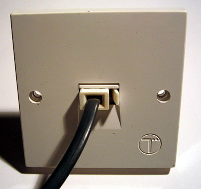
These allowed competitors to supply telephones for purchase and opened the telephone market in the UK to wider competition and innovation. However the wiring up to the master socket and the socket itself remains the property of the telephone line provider. With the LJU socket shown above, it was problematic to allow extension sockets to be connected to it's terminals. At this time it was common for extension adapter kits to be supplied, or for people to ignore this rule and connect their extension direct to the master socket.
Some LJU's (especially extension sockets) had screw terminations whilst most had Insulation Displacement Connections (IDC). IDC terminals allow for quick termination. The wire is forced, by the use of a special tool (Krone IDC Wire Inserter), into the slot of a strip of metal. The wire must be terminated with the insulation intact - the insulation holds the wire in the terminal by friction - and two wires can be terminated in one IDC connector. The terminals are not designed for repeated connection or disconnection.
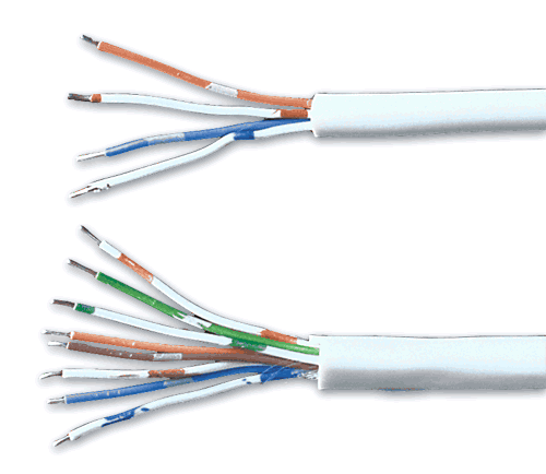
The sockets are wired together using CW1308 telephone cable, a multi-core cable of twisted pair design. Twisted pair was standardised because these meant that the same cable could be used for telephone system feature phones as well as standard analogue phones. The twisted pairs also allow for faster transmission of data, with minimal crosstalk.
Later on, to solve the issue with unauthorised connection to LJU sockets, during the late 1980's BT (British Telecommunications) introduced the NTE 5 (Network Termination Equipment) socket type, which is still in use today in various guises. This features a removable bottom half with the extension connections, the top half contains the provider's cable and connections, providing a clear demarcation line between provider responsibility and subscriber responsibility.
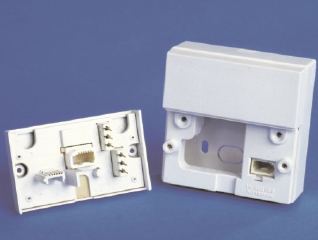
Every UK telephone system must have (at least) one master socket supplied by the provider, but can have any number of slave/secondary sockets (subject to maximum cable lengths and telephone REN numbers).
The master socket contains a 1.8µF capacitor to pass ringing current to the telephones, a 470k ohm resistor for testing purposes and a surge arrestor 11A or 26A to suppress high voltage spikes.
Secondary sockets have no electrical components.
Wiring and connecting an extension socket
Sockets are connected together by means of 6 wire (3 pair) CW1308 telephone cable (don't use cat5 or cat 6 cable for this). All of the secondary sockets are 'daisy chained' from the master.
Connections:
Provider's Line terminals |
Master Socket (extension connectors) |
Wiring |
Extension Socket |
|---|---|---|---|
| 1 | Green with white bands | 1 | |
| A | 2 | Blue with white bands | 2 |
| 3 | Orange with white bands | 3 | |
| PBX Earth | 4 | White with orange bands | 4 |
| B | 5 | White with blue bands | 5 |
| 6 | White with green bands | 6 |
Only connect two wires maximum to any IDC connector.
Terminals 2, 3 and 5 are used normally, 3 is the phone ringer terminal. Extension bells are wired off connections 3 and 5.
Terminals 1,4,and 6 are not generally used in the home. In fact some versions of the NTE5 / CTE 5 socket have now dispensed with terminals 1 and 6 altogether.
The incoming BT line wires can be any colour and polarity is not an issue. BT incoming pair cable from the roadside is a solid colour twisted pair cable:
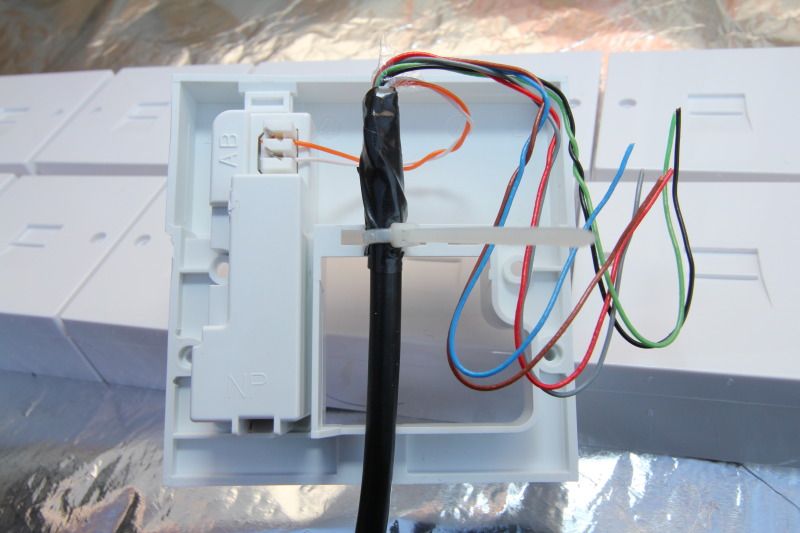
Troubleshooting
The customer can remove the front plate of the master socket and connect their extension wiring to the plate. The plate is then refitted, connection the wiring to the telephone line.
The plate locates in an internal socket which is also used as a test point.
In the event of any issues you will be asked to remove the front from your master socket and plug in your phone to this internal socket by the provider's helpline.
This helps the provider to eliminate any issues with dodgy cabling that they are not responsible for fixing. If the line works, then it is your wiring at fault - any wiring after the master socket is yours - whether or not you installed it.
If your house is fitted with any other type of connection, like the older LJU or line terminal box, you should ask your provider to fit an NTE 5 or CTE 5 master socket for you.
On older installations (pre-1980) cream or grey cables were used for internal wiring. They contained conductors coloured blue to pin 2, orange to pin 5, brown to pin 3 and green to pin 4 (if used), on some conversions green was used for pin 3 and brown for pin 4.
If you are having issues and have multiple telephones, check that the REN (Ringer Equivalence Number) for all of these phones added together does not exceed REN 4, the maximum for a single line.
